1. Article purpose[edit | edit source]
This article explains the boot chain of the STM32CubeMP13 package running on Arm® Cortex®-A7 core.
2. Overview[edit | edit source]
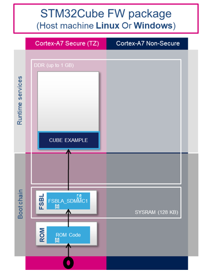
The STM32CubeMP13 package boot chain uses FSBLA_Sdmmc1 as the first stage bootloader to load the STM32CubeMP13 example present in external flash microSDTM card to DDR memory on the STM32MP135x-DK board.
FSBLA_SNOR is provided as an example for STM32MP13XX_CUSTOM_HW and can be a starting point for adaptation to your board for using QSPI-SNOR as a boot device.
The FSBLA_Sdmmc1 application source code is delivered in the package and is available in the directory Firmware/Projects/STM32MP135C-DK/Applications/FSBLA/FSBLA_Sdmmc1.
Also, its binary, FSBLA_Sdmmc1_A7_Signed.bin, is delivered as a part of the external loader package available in the directory Firmware/Projects/STM32MP135C-DK/External_Loader/SD_Ext_Loader.
This binary is programmed in a microSDTM card via STM32PRGFW_UTIL_MP13xx_CP_Serial_Boot.stm32 in serial boot mode.
On next boot from microSDTM card, it is used to load STM32CubeMP13 example or any test application from the microSDTM card to DDR.
Refer to How to load and start STM32CubeMP13 applications via microSD card for more explanations.

3. Boot chain components[edit | edit source]
3.1. ROM code[edit | edit source]
The ROM code is a piece of software that takes its name from the read-only memory (ROM) where it is stored. It fits in a few tens of KB and maps its data in embedded RAM. It is the first code executed by the processor, and it embeds all the logic needed to select the boot device (serial link or flash) from which the first-stage bootloader (FSBL) is loaded to the embedded RAM.
Most products require trust in the application running on the device, and the ROM code is the first link in the chain of trust that must be established across all started components. This trust is established by authenticating the FSBL before starting it. In turn, the FSBL and each following component authenticates the next one, up to a level defined by the product manufacturer.
In summary, the ROM code starts the processor in secure mode. It supports the FSBL authentication and decryption.
3.2. First stage bootloader for Arm Cortex-A (FSBLA)[edit | edit source]
The FSBLA is executed from the SYSRAM. This bootloader initializes part of the clock tree and the DDR controller. It sets SYSRAM and SDMMC in nonsecure.
|
Finally, the FSBLA reads from the boot interface (after reinitializing the boot interface SDMMC1. The first initialization is done by the ROM) and loads the STM32CubeMP13 example into the DDR external RAM and jumps to it.
|
|
3.3. STM32CubeMP13 example[edit | edit source]
The STM32CubeMP13 example is executed from the DDR external RAM. Any STM32CubeMP13 example can be loaded into DDR external RAM if it is properly linked into DDR memory. Refer to the build example for DDR and signing the example for more explanations.
4. MicroSDTM card flashlayout constraint[edit | edit source]
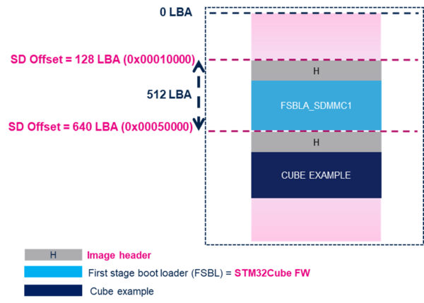
To boot a STM32CubeMP13 example from a microSDTM card, the card needs to contain these two binaries:
FSBLA_Sdmmc1: the first stage bootloader @128 logical block address (LBA). This block address is fixed address from where ROM code brings in the FSBLA.STM32CubeMP13 example: any example linked in DDR. By default, It is @640 logical block address(LBA) and can be modified in FSBLA_SDMMC code.
Both FSBLA_Sdmmc1 and STM32CubeMP13 example binaries are signed (binaries with image header). Refer to STM32CubeProgrammer signing tool or How to add STM32 header
