1. Article purpose[edit | edit source]
This article describes the configuration of the Cortex®-M0+ and its related resources, and how to run a Cortex®-M0+ firmware through a low power demonstration application. The purpose of this application is to demonstrate a low power use case and a communication use case between the Cortex®-M0+ and Cortex®-A35.
|
2. Introduction[edit | edit source]
The Cortex®-M0+ acts as a coprocessor with access to limited resources, peripherals, and memories. The Cortex®-M0+ processor is dedicated to executing small tasks that require few resources. It runs in a separate SmartRun domain, allowing other domains to be turned off to achieve low power consumption.
3. Resources access from Cortex®-M0+[edit | edit source]
3.1. Memories[edit | edit source]
The Cortex®-M0+ can only use the LPSRAM memories for a total of 32KB, with the following memory mapping:
- LPSRAM1 : 0x200C0000 - 0x200C1FFF (8KB)
- LPSRAM2 : 0x200C2000 - 0x200C3FFF (8KB)
- LPSRAM3 : 0x200C4000 - 0x200C7FFF (16KB)
| In the STM32MPU Embedded Software distribution, the memory mapping of the LPSRAM must necessarily be defined between 0x200C0000 and 0x200C7FFF. |
3.2. Peripherals[edit | edit source]
The Cortex®-M0+ can only access a limited set of peripherals:
- LPTIM3, LPTIM4, LPTIM5
- SPI8
- LPUART1
- I2C8
- ADF1C
- GPIOZ
- LPDMA
- RTC
- I3C4
- IPCC2
- EXTI2
- HSEM
3.3. Other resources[edit | edit source]
The Cortex®-M0+ can also access other resources such as:
- PWR
- CoreSight Debug through 2 ports:
- The SWD (Serial Wire Debug)
- The SWJ-DP (Serial Wire JTAG-Debug Port)
| The Cortex®-M0+ has no access to RCC resources (for clock configuration, for example). This implies that clock gating must be managed by the Cortex®-A35 (Linux kernel or OP-TEE). |
3.4. Security[edit | edit source]
All memories, peripherals, and resource access rights are managed by the Resource Isolation Framework (RIF) in the Cortex®-A35 OP-TEE.
3.4.1. Memories RIF configuration example[edit | edit source]
The OP-TEE STM32MP2_firewall_configuration of the LPSRAM memories must allow loading the M0+ firmware image by the Cortex®-A35 Linux kernel remoteproc framework and execution of the firmware on the Cortex®-M0+.
In the following OP-TEE device tree example, LPSRAM 1/2/3 (RISAL_ID 1/2/3 respectively) are configured as shared memory (subregion A and subregion B) between the Cortex®-A35 (RID_CID1) and Cortex®-M0+ (RIF_CID3):
	st,risal = <
		RISALPROT(RISAL_ID(1), RIFSC_RISAL_BLOCK_A, RIF_CID1, RIF_UNLOCK, RIF_NSEC, RIF_NPRIV, RIFSC_RISAL_SREN)
		RISALPROT(RISAL_ID(2), RIFSC_RISAL_BLOCK_A, RIF_CID1, RIF_UNLOCK, RIF_NSEC, RIF_NPRIV, RIFSC_RISAL_SREN)
		RISALPROT(RISAL_ID(3), RIFSC_RISAL_BLOCK_A, RIF_CID1, RIF_UNLOCK, RIF_NSEC, RIF_NPRIV, RIFSC_RISAL_SREN)
		RISALPROT(RISAL_ID(1), RIFSC_RISAL_BLOCK_B, RIF_CID3, RIF_UNLOCK, RIF_NSEC, RIF_NPRIV, RIFSC_RISAL_SREN)
		RISALPROT(RISAL_ID(2), RIFSC_RISAL_BLOCK_B, RIF_CID3, RIF_UNLOCK, RIF_NSEC, RIF_NPRIV, RIFSC_RISAL_SREN)
		RISALPROT(RISAL_ID(3), RIFSC_RISAL_BLOCK_B, RIF_CID3, RIF_UNLOCK, RIF_NSEC, RIF_NPRIV, RIFSC_RISAL_SREN)
	>;
3.4.2. Peripherals RIF configuration example[edit | edit source]
The RIF access rights are applied to the peripherals and their associated RCC registers. If the Cortex®-M0+ controls the peripheral, the Cortex®-A35 must configure the associated RCC registers before starting the Cortex®-M0+. For this reason, the peripherals' RIF access rights must be allowed for both the Cortex®-A35 and the Cortex®-M0+.
In the following example, the LPUART1 is configured without any filtering to allow access to LPUART1 by both the Cortex®-A35 and the Cortex®-M0+:
&rifsc {
	st,protreg = <
	[...]
		RIFPROT(STM32MP25_RIFSC_LPUART1_ID, RIF_UNUSED, RIF_UNLOCK, RIF_NSEC, RIF_NPRIV, RIF_UNUSED, RIF_SEM_DIS, RIF_CFDIS)
	[...]
	>;
	st,glocked = <RIFSC_RIMU_GLOCK>;
};
3.5. Low power constraints[edit | edit source]
The Cortex®-M0+ can be used during low power modes, while the Cortex®-A35 and Cortex®-M33 are stopped. A dedicated autonomous mode is available for each peripheral that can be allocated to the Cortex®-M0+ to avoid stopping peripheral clocks during Cortex®-A35 low power.
| On ecosystem release v6.0.0 |
4. Linux Kernel configuration[edit | edit source]
- To manage the Cortex®-M0+, activate the Cortex®-M0+ remoteproc driver by enabling the STM32_M0_RPROC build configuration.
- To communicate with the Cortex®-M0+, activate the mailbox char device client by enabling the MAILBOX_CDEV build configuration.
5. Linux Kernel device tree configuration[edit | edit source]
The Cortex®-M0+ lifecycle is managed by the Linux kernel remoteproc framework. To configure the Cortex®-M0+, you mainly need:
- to define the memory mapping,
- to define the m0_rproc node in the device tree,
- to define the mailbox char device client node configuration.
5.1. Memory configuration[edit | edit source]
In the STM32MPU Embedded Software distribution, the default memory configuration is split into 3 memory regions that can be customized:
- Code : 16KB (LPSRAM1 & LPSRAM2)
- Data : 8KB (LPSRAM3)
- Shared Memory : 8KB (LPSRAM3)
The shared memory is used to share data between Cortex®-M0+ and Cortex®-A35 through interprocessor communication and mailbox mechanisms.
reserved-memory {
	[...]

	cm0_cube_fw: cm0-cube-fw@200C0000 {
		compatible = "shared-dma-pool";
		reg = <0x0 0x200C0000 0x0 0x4000>;
		no-map;
	};

	cm0_cube_data: cm0-cube-data@200C4000 {
		compatible = "shared-dma-pool";
		reg = <0x0 0x200C4000 0x0 0x2000>;
		no-map;
	};

	ipc_shmem_2: ipc-shmem-2@200C6000{
		compatible = "shared-dma-pool";
		reg = <0x0 0x200C6000 0x0 0x2000>;
		no-map;
	};
};
| This memory mapping needs to be aligned with the Cortex®-M0+ Cube Firmware memory mapping (linker script). |
5.2. Remoteproc configuration[edit | edit source]
- The memory-region property should list the memories used for firmware execution.
- The clocks property should list the peripheral clocks used by the Cortex®-M0+.
&m0_rproc {
	memory-region = <&cm0_cube_fw>, <&cm0_cube_data>;
	clocks = <&rcc CK_CPU3>,              /* Enable Cortex-M0+ clock */
		 <&rcc CK_CPU3_AM>,               /* Enable Cortex-M0+ autonomous mode */
		 <&rcc CK_LPUART1_C3>,            /* Allocate LPUART1 to Cortex-M0+ */
		 <&rcc CK_KER_LPUART1>,           /* Enable LPUART1 clock */
		 <&rcc CK_LPUART1_AM>,            /* Enable LPUART1 autonomous mode */
		 <&scmi_clk CK_SCMI_IPCC2>,       /* Enable IPCC2 clock */
		 <&scmi_clk CK_SCMI_IPCC2_AM>;    /* Enable IPCC2 autonomous mode */
	status = "okay";
};
5.3. Mailbox client configuration[edit | edit source]
- The memory-region property should list the memory used for interprocessor communication (shared memory).
mbox_client: mailbox-client@1 {
	compatible = "mbox-cdev";
	reg = <1 0>;
	memory-region = <&ipc_shmem_2>;
	mboxes = <&ipcc2 0>;
	mbox-names = "rx-tx";
	status = "okay";
};
6. Cortex®-M0+ demonstration[edit | edit source]
The Cortex®-M0+ demonstration shows the Cortex®-A35 waking up from low power mode (LP-Stop2) triggered by the Cortex®-M0+.
The demonstration application includes:
- Starting the Cortex®-M0+ firmware through the remoteproc driver.
- Configuring a wakeup delay in the Cortex®-M0+ firmware from Linux userland (Cortex®-A35) using IPCC communication, shared memory, and mailbox mechanisms.
- Setting the LP-Stop2 low power mode.
- Waking up the Cortex®-A35 from the Cortex®-M0+ firmware via an interrupt after the programmed delay expires.
6.1. STM32Cube Firmware application[edit | edit source]
The Cortex®-M0+ STM32Cube Firmware application is available as an example in the STM32CubeMP2 Firmware Package. It allows waking up the Cortex®-A35 from low power mode after a programmed delay.
This application uses the following features:
- LPUART1: to print messages on the console.
- IPCC2: to send/receive notifications between Cortex®-M0+ and Cortex®-A35 through interprocessor communication (interrupt).
- Shared Memory: to share data between Cortex®-M0+ and Cortex®-A35.
The purpose of this application is to:
- Initialize LPUART1 for printing messages on the console.
- Initialize IPCC2 for communication between Cortex®-M0+ and Cortex®-A35.
- Print a message on LPUART1 every 2 seconds.
- Wait for an IPCC2 interrupt corresponding to a message received in shared memory from Cortex®-A35.
- Once the IPCC2 interrupt is received, the firmware:
- Reads the first 4 bytes from shared memory, representing the delay before sending a notification to Cortex®-A35.
- Starts a delay with the value read from shared memory.
- Once the delay has elapsed, sends a notification through IPCC2 to wake up Cortex®-A35.
- Once the IPCC2 interrupt is received, the firmware:
- Continues printing the default message on LPUART1 and waits for new messages from Cortex®-A35.
6.2. Board and connectors[edit | edit source]
6.2.1. STM32MP257x-EV1 Evaluation board  [edit | edit source]
Main access to Cortex®-M0+ is through the MikroBUS connector.
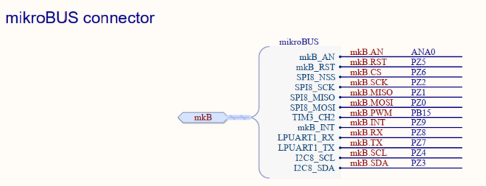
To use LPUART1, you need to Connect a 3-wire USB-to-TTL Serial UART debug cable to the MikroBUS connector LPUART1_TX, LPUART1_RX, and GND.
6.2.2. STM32MP257x-DK Discovery kit [edit | edit source]
Main access to Cortex®-M0+ is through the GPIO expansion connector.

To use LPUART1, you need to connect a 3-wire USB-to-TTL Serial UART debug cable to the GPIO expansion connector EXP_GPIO25(LPUART1_TX), EXP_GPIO26(LPUART1_RX), and GND.
6.3. How to debug Cortex®-M0+[edit | edit source]
Debugging the Cortex®-M0+ can be done in two ways depending on the Cortex®-A35 state:
- When Cortex®-A35 is running, debug Cortex®-M0+ via the STLINK connector.
- When Cortex®-A35 is in low power mode, debug Cortex®-M0+ via the SWD port.
To use the SWD interface, you need to:
- Connect the debugger to the MikroBUS connector pins MISO, MOSI, 3.3V, and GND.
- Enable the SWD debug interface for Cortex®-M0+ by clearing the bit DBG_SWD_SEL_N in the DBGMCU_CR register.

6.4. How to run the Cortex®-M0+ demonstration application[edit | edit source]
The Cortex®-M0+ firmware image must be copied to the /lib/firmware folder in the Linux root filesystem. By default, the Cortex®-M0+ firmware is named CM0PLUS_Demo_NonSecure.elf.
- Start from the following path and verify that the Cortex®-M0+ firmware is available:
cd /lib/firmware
- Stop the M33 firmware:
echo stop > /sys/class/remoteproc/remoteproc0/state
- Configure the M0+ firmware:
echo CM0PLUS_Demo_NonSecure.elf > /sys/class/remoteproc/remoteproc1/firmware
- Start the M0+ firmware:
echo start > /sys/class/remoteproc/remoteproc1/state
[ 1245.086086] remoteproc remoteproc1: powering up m0
[ 1245.120304] remoteproc remoteproc1: Booting fw image CM0PLUS_Demo_NonSecure.elf, size 1017852
[ 1245.123454] remoteproc remoteproc1: remote processor m0 is now up
- Enable IPCC2 wakeup source for A35 wakeup:
echo enabled > /sys/devices/platform/soc@0/46250000.mailbox/power/wakeup
- Configure delay to Cortex®-M0+ before waking up Cortex®-A35 (e.g., 7 seconds):
echo 7 > /dev/mailbox0
Cortex®-M0+ logs from LPUART1:
**** CM0PLUS Example application ****
(1) Hello from CM0+
(2) Hello from CM0+
(3) Hello from CM0+
(4) Hello from CM0+
(5) Hello from CM0+
(5) A35 wakeup request in 7s
- Set Cortex®-A35 to low power mode (for 30 seconds):
rtcwake --date +30sec -m mem
Cortex®-A35 logs from Linux console:
rtcwake: assuming RTC uses UTC ...
rtcwake: wakeup from "mem" using /dev/rtc0 at Tue Oct  8 16:44:29 2024
[  414.922335] PM: suspend entry (deep)
[  414.922538] Filesystems sync: 0.000 seconds
[  414.960147] Freezing user space processes
[  414.962082] Freezing user space processes completed (elapsed 0.001 seconds)
[  414.965543] OOM killer disabled.
[  414.968675] Freezing remaining freezable tasks
[  414.974403] Freezing remaining freezable tasks completed (elapsed 0.001 seconds)
[  414.985780] stm32-dwmac 482d0000.eth2 end0: FPE workqueue stop
[  414.986671] stm32-dwmac 482c0000.eth1 end1: FPE workqueue stop
[  415.070706] Disabling non-boot CPUs ...
[  415.072458] psci: CPU1 killed (polled 0 ms)
INFO:    Entering LP_Stop2 low power mode
- Cortex®-A35 wakeup:
Cortex®-M0+ logs from LPUART1:
(5) A35 wakeup request done!
(6) Hello from CM0+
Cortex®-A35 logs from Linux console:
[  415.073956] Enabling non-boot CPUs ...
I/TC: Secondary CPU 1 initializing
I/TC: Secondary CPU 1 switching to normal world boot
[  415.085464] Detected VIPT I-cache on CPU1
[  415.085540] CPU1: Booted secondary processor 0x0000000001 [0x411fd040]
[  415.086106] CPU1 is up
[  415.095505] i2c 0-001a: Unbalanced pm_runtime_enable!
[  415.137097] dwmac4: Master AXI performs any burst length
[  415.137154] stm32-dwmac 482c0000.eth1 end1: No Safety Features support found
[  415.345753] stm32-dwmac 482c0000.eth1 end1: IEEE 1588-2008 Advanced Timestamp supported
[  415.348476] stm32-dwmac 482c0000.eth1 end1: FPE workqueue start
[  415.354080] stm32-dwmac 482c0000.eth1 end1: configuring for phy/rgmii-id link mode
[  415.577092] dwmac4: Master AXI performs any burst length
[  415.577134] stm32-dwmac 482d0000.eth2 end0: No Safety Features support found
[  415.583804] stm32-dwmac 482d0000.eth2 end0: IEEE 1588-2008 Advanced Timestamp supported
[  415.591954] stm32-dwmac 482d0000.eth2 end0: FPE workqueue start
[  415.597751] stm32-dwmac 482d0000.eth2 end0: configuring for phy/rgmii-id link mode
[  416.086930] onboard-usb-hub 1-1: reset high-speed USB device number 2 using ehci-platform
[  416.352327] OOM killer enabled.
[  416.352360] Restarting tasks ... done.
[  416.359329] random: crng reseeded on system resumption
[  416.366896] PM: suspend exit
7. Code source[edit | edit source]
7.1. Linux kernel[edit | edit source]
drivers/remoteproc/stm32_m0_rproc.c drivers/mailbox/mailbox-client_cdev.c arch/arm64/boot/dts/st/stm32mp257f-ev1.dts arch/arm64/boot/dts/st/stm32mp257f-dk.dts (ecosystem release ≥ v6.1.0)
7.2. STM32Cube applications[edit | edit source]
Projects/STM32MP257F-EV1/Demonstrations/CM0PLUS_DEMO Projects/STM32MP257F-DK/Demonstrations/CM0PLUS_DEMO (ecosystem release ≥ v6.1.0