1. TouchGFX MPU Addon Documentation[edit | edit source]

If you are new to this documentation and/or TouchGFX MPU development, we recommend that you read on to get an overview of what this documentation has to offer.
1.1. About this documentation[edit | edit source]
The main documentation for the site is organized into the following sections:
- Introduction - read surface-level information on TouchGFX MPU Addon and installation guide.
- Getting Started – how to get started with the TouchGFX development for the newly supported MPU devices.
- Debugging - how to debug a TouchGFX MPU application using the STM32CubeIDE tool.
1.2. Target User[edit | edit source]
The TouchGFX MPU Addon documentation is targeting software developers with a basic skill set within TouchGFX GUI development on STM32. Newcomers to Embedded GUI Development are not supported in this documentation; we recommend them to go through TouchGFX Official documentation before reading this documentation to get step by step guides and tutorials support and learn in TouchGFX development as well.
We would really like to improve this documentation in any way possible. If you don’t understand something or cannot find what you are looking for in the docs, help us make the documentation better by letting us know in the forum
2. Introduction[edit | edit source]
An introduction to the TouchGFX MPU Addon.
2.1. What is TouchGFX MPU Addon?[edit | edit source]
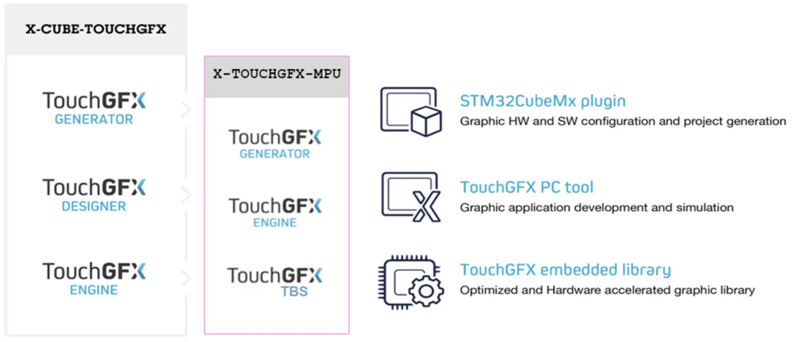
TouchGFX is delivered as one X-Cube package the X-Cube-TouchGFX. Using TouchGFX, you have all you need to do a full implementation of your GUI application for STM32 MCU based hardware. TouchGFX nativity doesn’t support MPU devices.
The TouchGFX MPU Addon comes to offer the support for STM32 MPU devices for TouchGFX. With this Addon you have all you need to do full implementation of your GUI application for STM32 MPU based hardware.
TouchGFX MPU Addon consists of three main updates for the TouchGFX distribution.
- TouchGFX Generator Update for MPU: An update for the STM32CubeIDE code generator tool where the user can design and generate a TouchGFX GUI using the Designer Tool for their STM32-based MPU hardware.
- TouchGFX Engine for MPU: The TouchGFX C++ framework optimized for STM32 microprocessors.
- TouchGFX TBS for newly supported MPU products: An easy-to-use Target Board Support for the newly supported MPU board with "STM32Cube MPU" configuration that lets you create and build your TouchGFX GUI application for STM32 MPU products.
2.2. Prerequisites[edit | edit source]
TouchGFX MPU Addon is primarily developed for use on Windows 10. The TouchGFX MPU Addon is only running on Windows, it also requires having TouchGFX already installed on the host machine and additional Tools are also required.
2.3. Using TouchGFX MPU Addon[edit | edit source]
The TouchGFX MPU Addon is now available for TouchGFX version 4.24.0.
TouchGFX MPU Addon will bring all the basic software required for GUI development for STM32 MPU devices. You need to install the corresponding TouchGFX version which matches the TouchGFX MPU Addon version before proceeding to the Addon installation.
See the Installation section for instructions on installation of TouchGFX MPU Addon and required tools for flashing code.
2.4. Installation[edit | edit source]
In this section we will show you how to install TouchGFX MPU Addon as well as all the necessary Software Tools required to start your embedded graphics development for the STM32-based MPU devices.
2.4.1. Getting X-TOUCHGFX-MPU[edit | edit source]
TouchGFX MPU Addon is bundled in a compressed (zipped) package called X-TOUCHGFX-MPU. This package is most easily downloaded and installed directly from the ST.com official website to anywhere on your hard drive and extract it.
Downloading X-TOUCHGFX-MPU from st.com
2.4.2. Installing TouchGFX MPU Addon[edit | edit source]
Inside the unpacked/extracted X-TOUCHGFX-MPU distribution you will find the TouchGFX MPU Addon.msi installer in the following path:
Utilities\PC_Software\Addons
Double-clicking the .msi file will bring up the installer. Follow the instructions to complete the installation process.
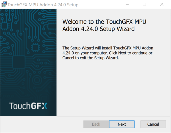
TouchGFX MPU Addon Installer
Make sure to select a valid TouchGFX installation folder otherwise an error will be raised.
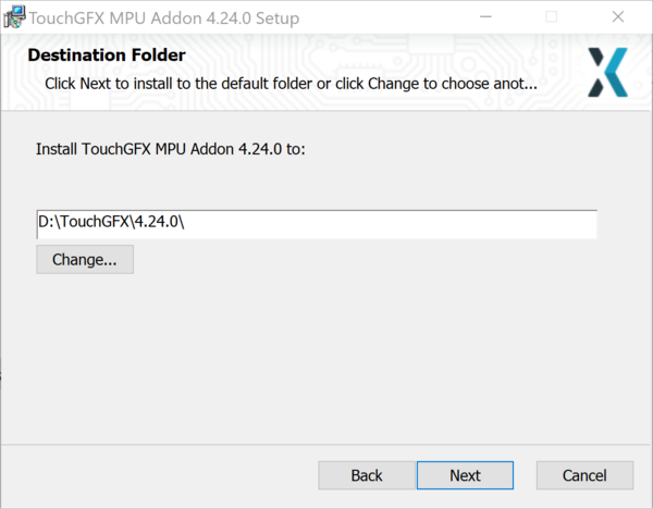
Installation folder selection
If the selected folder doesn’t include a valid TouchGFX installation or if it includes a non-matching TouchGFX installation version, the installation will be aborted.
You need to install the STM32CubeProgrammer tool to be able to flash your board.
2.4.3. Installing STM32CubeIDE[edit | edit source]
After downloading STM32CubeIDE for Windows® host PC version 1.15.0 from STM32CubeIDE location, simply open the downloaded .exe file and follow the instructions to complete the installation process.
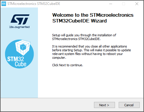
Installing STM32CubeIDE
You can refer to STM32CubeIDE installation guide (UM2563)) available on st.com. This tool is used to build the generated GUI application code, flash it and debug the execution too.
You can refer to Debugging GUI Application using STM32CubeIDE section in this documentation.
You need to install the STM32CubeProgrammer tool to be able to flash your board.
2.4.4. Installing STM32CubeProgrammer[edit | edit source]
After downloading STM32CubeProgrammer version 2.16.0 from STM32CubeProgrammer download location, uncompress the downloaded .zip file and launch the .exe installer file. Then Follow the instructions to complete the installation process.
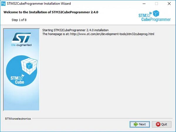
Installing STM32CubeProgrammer
Instructions to follow for using the STM32CubeProgrammer can be found in user manual, [STM32_MPU_resources#UM2237| UM2237]] available from ST web site, or in STM32CubeProgrammer#How_to_flash_with_STM32CubeProgrammer article.
3. Getting Started[edit | edit source]
A prerequisite to get started using TouchGFX for STM32 MPU devices is to install all software components required, which are described in the previous #Installation.
After this is done you are ready to begin your very first TouchGFX project for STM32 MPU products. It is highly recommended that you read some key sections of TouchGFX Documentation to get familiar with the very basic of TouchGFX concepts. The most essential section is the Development Introduction which will give you an introduction to the software and hardware components needed for a complete TouchGFX project and the activities and tools involved in creating them. It also describes how to get started doing a fast prototype using premade components.
In addition, this documentation would help you to start developing TouchGFX application for STM32 MPU devices, in particular, GUI applications that are targeting the STM32MP135F-DK - Discovery kit product.
The TouchGFX MPU Addon provides you with the TouchGFX board setup for the STM32MP135F-DK board.
3.1. TouchGFX Quick Start[edit | edit source]
To create a TouchGFX project based on a TouchGFX Board Setup go ahead and start the TouchGFX Designer.
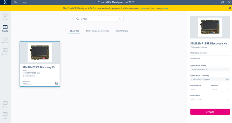
Creating an application with STM32MP135F-DK TouchGFX Board Setup
3.1.1. Combining TouchGFX Board Specific with Examples or Demo[edit | edit source]
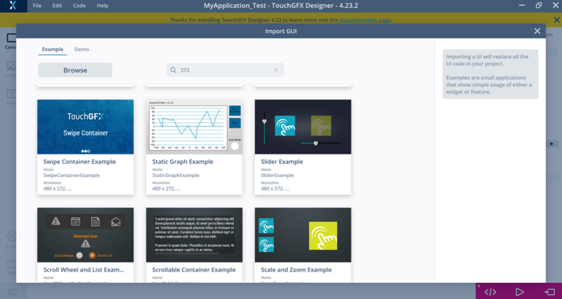
On the lobby in TouchGFX Designer you can select from a wide range of examples and demos to start from. You can combine this with board specific code for a range of STM32 MPU based Boards, so you can have an UI running on the embedded hardware right away.
 ]
]
Importing a TouchGFX example for STM32MP135F-DK TBS
These are available in the Demos section under Board Specific Demo.
3.1.2. Combining TouchGFX Board Specific with Demos[edit | edit source]
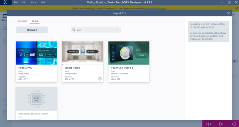
Aside from being able to combine a TouchGFX Board Setup with an Example or a Demo, TouchGFX Designer also includes some out of the box demos for specific STM32 Evaluation and Discovery Kits.
These are available in the Demos section under Board Specific Demo.
 ]
]
Importing a TouchGFX Demo for STM32MP135F-DK TBS
Make sure to select a compatible Demo and/or Example which the framebuffer color depth and resolution matches the selected STM32 MPU TouchGFX Board Setup.
3.1.3. Building GUI application with the TouchGFXDesigner[edit | edit source]
You can use the ‘Program and Run Target’ button or press your keyboard function key ‘F6’ in the TouchGFXDesigner to build and program your GUI application.
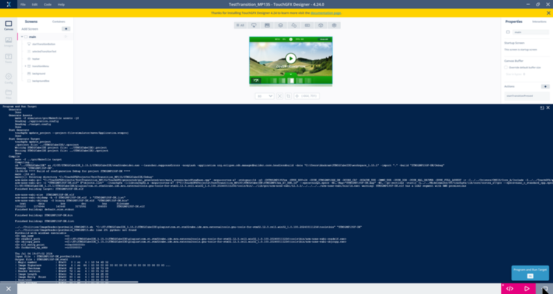 ]
]
Program and Run the TouchGFX Application using the TouchGFXDesigner Tool
This would require having the STM32CubeIDE and STM32CubeProgrammer Tools installed in the default locations.
Before starting the build and the programming of the application, please make sure to switch the board in ‘programming mode’ by changing the SW1 boot pins configuration and reset the board to get it ready for programming.
For more details on how to setup the Boot pins configuration please refer to ‘Setting the MPU board in programming mode’ section in this documentation.
To Run your application, you need to switch back your board to boot from the SD card.
3.1.4. Building GUI application with STM32CubeIDE[edit | edit source]
The build and ‘Run Target’ using Makefile (GCC) through the TouchGFX Designer are not supported for the MPU devices. Therefore, only code generation is to be performed using the Tool.
To build your generated GUI application, you will need to open the updated STM32CubeIDE project file and start the build. Only STM32CubeIDE building tool is supported for now for STM32 MPU devices.
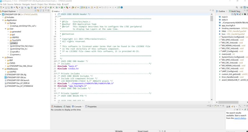 ]
]
Building a TouchGFX GUI application for STM32MP135F-DK TBS
After building your application, the application binary file ‘STM32MP135F-DK.stm32’ is first signed then generated in the below path in your project folder.
Project Folder>\Binary\apps\STM32MP135F-DK.stm32
You need now to program your board using either the STM32CubeProgrammer Tool or you can use the packaged bath script ‘Program_STM32MP135F-DK.bat’ with the STM32 MPU TBS to automatically program the board.
3.1.5. Flashing the GUI application[edit | edit source]
Before flashing your application on the MPU board, you need to configure your board to force USB boot for programming mode. This would require changing the configuration of the boot pins on the board.
The GUI application will be programmed into the SD card. Make sure to have SD card already inserted in the board before starting the programming.
3.1.5.1. Board connection[edit | edit source]
Refer to the STM32MP135x-DK_-_hardware_description#Board_connection for more details on how to connect your board to the host machine and get it ready for flashing and logging traces on your host machine.
The connections shown in the picture below are the ones recommended to start with the STM32MP135F-DK Discovery kits.
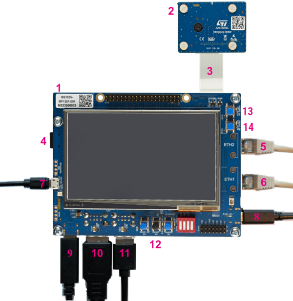
| 1 | MB1635 mother board - STM32MP135F 11x11, PMIC, DDR3 | 8 | USB Type-C™ (power 5V-3A) |
|---|---|---|---|
| 2 | MB1897 camera module | 9 | USB Type-C™ (DRP) |
| 3 | Camera module flat cable | 10 | 1st dual USB Type-A (host) → keyboard, mouse, or USB driver |
| 4 | microSD™ card slot | 11 | 2nd dual USB Type-A (host) → keyboard, mouse, or USB driver |
| 5 | Ethernet 2 → Network | 12 | Reset button |
| 6 | Ethernet 1 → Network | 13 | User button (USER1) |
| 7 | USB Micro-B (STLINK-V3E) → PC Virtual COM port and debug | 14 | User button (USER2) |
Recommended connections for the STM32MP135F-DK Board
3.1.5.2. Setting the MPU board in programming mode[edit | edit source]
At startup, the boot pins select the boot source used by the internal boot ROM. Below table describes the configurations of the boot pins for the STM32MP135F-DK board.

Boot mode pins for the STM32MP135F-DK board
The board includes a switch (SW1 for the STM32MP135F-DK board) allowing easy board boot configuration setup. You need to power off the board before changing the boot configuration mode.
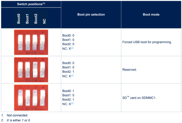
Boot mode switch SW1 on the STM32MP135F-DK board
Please refer to the MPU Board User Manual document available on ST website for more details on how to prepare your board for code programming.
3.1.5.3. Flashing the GUI application using the script[edit | edit source]
The script is performing STM32CubeProgrammer commands and is provided in the below location within your project file.
Project Folder>\Binary\Program_STM32MP135F-DK.bat
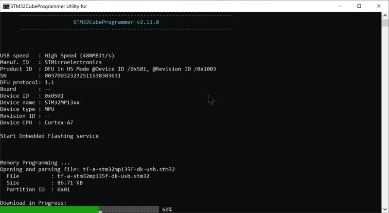
Once the board is ready for programming, you can run the script and wait until the programming is completed.
 ]
]
Flashing the MPU board using the providing programming script
Now you will need to revert your board configuration to boot from SD Card to run your application.
4. Debugging[edit | edit source]
A prerequisite to get started with TouchGFX for STM32 MPU devices application debugging is to flash the board with the generated binary files,which are described in the #Flashing the GUI application using the script.
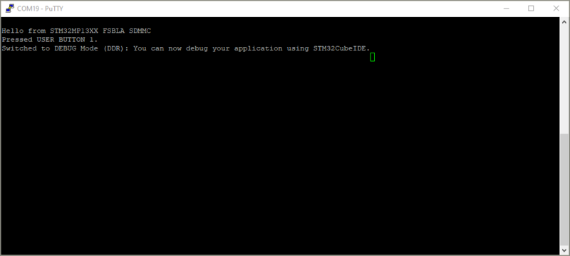
You can switch to DEBUG Mode just after rebooting the board and by pressing (or keep pressing) the USER BUTTON 1. This will setup the board in Debug mode and will break the execution until getting the GDB debugger connected to the board.
You should get the message below when the board is switched to Debug mode.
 ]
]
Board switched to DEBUG Mode
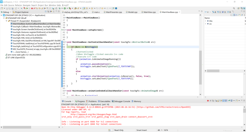
You can then start the Debugger in the STM32CubeIDE tool and connect to the board and debug the execution. The code will be copied and then executed from the DDR memory.
 ]
]
STM32CubeIDE Debugger
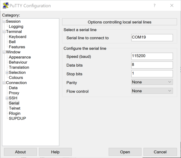
You can use Putty or Tera Term to get traces on the UART output and check printed messages on the console. The UART configuration (for Putty) should look as below.
 ]
]
Serial Port configuration for UART tracing