Registered User |
Registered User Tag: 2017 source edit |
||
| (46 intermediate revisions by 5 users not shown) | |||
| Line 1: | Line 1: | ||
<noinclude>{{ApplicableFor | <noinclude>{{ApplicableFor | ||
|MPUs list=STM32MP13x, STM32MP15x | |MPUs list=STM32MP13x, STM32MP15x, STM32MP21x, STM32MP23x, STM32MP25x | ||
|MPUs checklist=STM32MP13x, STM32MP15x | |MPUs checklist=STM32MP13x, STM32MP15x, STM32MP21x, STM32MP23x, STM32MP25x | ||
}}</noinclude> | }}</noinclude> | ||
This article gives information about the Linux<sup>®</sup> regulator framework. | This article gives information about the Linux<sup>®</sup> regulator framework. | ||
It explains how to activate voltage and current regulators and, based on examples, how to control them. | |||
== | ==Framework purpose== | ||
The objective of this chapter is to give general information about the regulator framework. | |||
Some documentation on the Linux regulator framework is provided with the {{DocSource| domain=Linux kernel | path= power/regulator/overview.html | text=Linux documentation}} or in code source power/regulator/overview.rst <ref>kernel documentation overview: {{CodeSource | Linux kernel | Documentation/power/regulator/overview.rst| Documentation/power/regulator/overview.rst}}</ref> | Some documentation on the Linux regulator framework is provided with the {{DocSource| domain=Linux kernel | path= power/regulator/overview.html | text=Linux documentation}} or in code source power/regulator/overview.rst <ref>kernel documentation overview: {{CodeSource | Linux kernel | Documentation/power/regulator/overview.rst| Documentation/power/regulator/overview.rst}}</ref> | ||
The power supplies can be provided by various blocks: | The power supplies can be provided by various blocks: | ||
* External single regulators: | * External single regulators, controlled by GPIO , I2C: | ||
** Low-dropout regulators (LDO) | ** Low-dropout regulators (LDO) | ||
** BUCKs (DC-to-DC power converter) | ** BUCKs (DC-to-DC power converter) | ||
** Switches | ** Switches | ||
* A Power Management Integrated Circuit (PMIC) that integrates several LDO and BUCKS | * A [[PMIC_hardware_components|Power Management Integrated Circuit (PMIC)]] that integrates several LDO and BUCKS | ||
* Internal regulators from the microprocessor device internal blocks: | * Internal regulators from the microprocessor device internal blocks: | ||
| Line 31: | Line 23: | ||
** [[VREFBUF internal peripheral|VREFBUF peripheral]] | ** [[VREFBUF internal peripheral|VREFBUF peripheral]] | ||
* Secure regulators provided by [[OP-TEE overview|OP-TEE]] with [[SCMI_overview|SCMI regulator drivers]] | * Secure regulators provided by [[STM32 MPU OP-TEE overview|OP-TEE]] with [[SCMI_overview|SCMI regulator drivers]] | ||
All the regulators are implemented and controlled under the standard Linux regulator framework. | All the regulators are implemented and controlled under the standard Linux regulator framework. | ||
== | == System overview == | ||
[[File:regulators.png|link=]] | [[File:regulators.png|link=]] | ||
==== | === Components description === | ||
''From client application to hardware'' | |||
* '''Regulator consumers''' (Kernel Space): The devices correspond to internal or external peripherals of the microprocessor device ( ADC, SDCARD, USB, ETHERNET... ). Each peripheral that needs a power supply to operate must enable it. | |||
* '''Regulator framework core''' (Kernel Space): The core manages all the regulators as described in {{DocSource| domain=Linux kernel | path= power/regulator/overview.html | text=Linux documentation}}. A consumer request is not handled directly by a regulator driver. It is handled by the core that can arbitrate requests between consumers in order to save power. | |||
* '''Regulator drivers''' (Kernel Space): A regulator that can be controlled (enable/disable, adjust voltage...) needs a driver to operate. This is the role of the regulator driver. A driver can also send notifications like over current or over temperature. [[SCMI overview|SCMI]] provide accesses to regulators that are not handled in Linux. | |||
* '''Microprocessor device internal regulators''' (Hardware): This corresponds to the regulators integrated to the microprocessor device. Those regulators supply mainly the USB and ADC peripherals provided by [[PWR internal peripheral|PWR]] and [[VREFBUF internal peripheral|VREFBUF]]. | |||
* '''External devices''' (Hardware): external regulators. This corresponds to physical components that provide the various power supplies on the board, for example [[PMIC_hardware_components|STMicrolectronics PMIC]] or GPIO controlled regulator. | |||
Notes: | Notes: | ||
* The kernel contains generic drivers for GPIO controlled regulators. | * The kernel contains generic drivers for GPIO controlled regulators. | ||
* The internal regulators of the microprocessor device are implemented in the STM32 machine. | * The internal regulators of the microprocessor device are implemented in the STM32 machine. | ||
=== | === API description === | ||
Depending on needs and the caller location (kernel space or user space), several APIs are available to control a regulator: | |||
=== | * '''User space API:''' The regulator framework offers a sysfs interface that can be used for monitoring. It is not possible to control a regulator via the sysfs. See {{DocSource| domain=Linux kernel | path= admin-guide/abi-testing.html#abi-file-testing-sysfs-class-regulator | text=documentation}} defined in {{CodeSource | Linux kernel | Documentation/ABI/testing/sysfs-class-regulator}} for details. | ||
The | *'''Kernel space API''': | ||
** The consumer interface allows to control a regulator (enable/disable, set voltage...), and to register to a notification service, see kernel documentation {{DocSource| domain=Linux kernel | path= power/regulator/consumer.html | text=consumer.rst}} <ref>Consumer API documentation: {{CodeSource | Linux kernel | Documentation/power/regulator/consumer.rst}}</ref> | |||
** The regulator driver API provides API to the regulators driver, see kernel documentation {{DocSource| domain=Linux kernel | path= power/regulator/regulator.html | text=regulator.rst}} <ref>Driver API documentation: {{CodeSource | Linux kernel | Documentation/power/regulator/regulator.rst}}</ref> | |||
*'''Debugfs API''': provides only information about regulator configuration, see [[#How to trace]] for example. | |||
== Configuration == | |||
=== Kernel configuration === | |||
Regulator framework is activated by default in ST deliveries. Nevertheless, if a specific configuration is needed, this section indicates how regulator drivers can be activated/deactivated in the kernel. | |||
Activate regulators driver in kernel configuration with Linux Menuconfig tool: [[Menuconfig or how to configure kernel]] | |||
Device Drivers ---> | |||
[*] Voltage and Current Regulator Support ---> | |||
[ ] Regulator debug support | |||
<*> Fixed voltage regulator support | |||
<*> Regulator protection consumer | |||
< > Virtual regulator consumer support | |||
< > Userspace regulator consumer support | |||
.... | |||
<*> SCMI based regulator driver | |||
.... | |||
<M> STMicroelectronics STM32 BOOSTER | |||
<M> STMicroelectronics STM32 VREFBUF | |||
[*] STMicroelectronics STM32 PWR | |||
<*> STMicroelectronics STPMIC1 PMIC Regulators | |||
... | |||
Regulators framework supports several drivers. User can select from there any driver among the supported devices; please refer to [[SCMI overview]], [[PMIC_hardware_components]] or [[:Category:Linux_Operating_System|Linux driver]] articles for each peripheral. | |||
=== Device tree configuration === | |||
Binding documentation: {{CodeSource | Linux kernel | Documentation/devicetree/bindings/regulator/regulator.yaml | regulator.yaml}} | |||
The device tree describes regulators and consumers: | |||
* A regulator provides a supply. | |||
* | * A consumer uses a supply. | ||
* | When possible, the supply name comes from the electrical schematics of the board. | ||
The regulator framework also handles the '''power management'''. | |||
* '''Runtime''': The consumers should disable the regulators that are not needed and the core disables a regulator as soon as it is not requested by any consumer.<br/>This can be avoided by the usage of {{highlight|regulator-always-on}} property in the device-tree. | |||
* '''Suspend''' : The regulator framework offers the possibility to define suspend states for regulators. This is only possible if the driver allows it. | |||
The regulator suspend sate is no more handled by the linux kernel in OpenSTLinux distribution.<br/> {{highlight|regulator-state-standby}}, {{highlight|regulator-state-mem}}, {{highlight|regulator-state-disk}} are used to define the state of the regulators during suspend. | |||
{{highlight|regulator-state-standby}} { | |||
regulator-on-in-suspend; | |||
regulator-suspend-microvolt = <900000>; | |||
regulator-mode = <8>; | |||
}; | |||
{{highlight|regulator-state-mem}} { | |||
regulator-off-in-suspend; | |||
}; | |||
* The regulator runtime strategy does not apply to suspend. With "regulator-on-in-suspend", the regulator is enabled in suspend even if no consumer uses it. | |||
* "regulator-always-on" does not apply to suspend states. | |||
== How to use framework == | |||
=== How to define regulator in device tree === | |||
The | The regulators have generic parameters defined in the binding documentation: {{CodeSource | Linux kernel | Documentation/devicetree/bindings/regulator/regulator.yaml|regulator.yaml}}. | ||
All these device tree properties are managed by Linux kernel framework and are some of them are also supported in other OpenSTLinux components: | |||
* in TF-A and in OP-TEE: {{highlight|regulator-always-on}}, {{highlight|regulator-enable-ramp-delay}} | |||
* in OP-TEE: {{highlight|regulator-ramp-delay}}, {{highlight|regulator-min-microvolt}}, {{highlight|regulator-max-microvolt}} | |||
==== Fixed regulator ==== | |||
usb otg vbus: | usb otg vbus: | ||
| Line 122: | Line 138: | ||
Binding documentation:{{CodeSource | Linux kernel | Documentation/devicetree/bindings/regulator/fixed-regulator.yaml | fixed-regulator.yaml}} | Binding documentation:{{CodeSource | Linux kernel | Documentation/devicetree/bindings/regulator/fixed-regulator.yaml | fixed-regulator.yaml}} | ||
==== Gpio controlled regulator ==== | |||
sdcard level shifter: | sdcard level shifter: | ||
| Line 141: | Line 157: | ||
Binding documentation:{{CodeSource | Linux kernel | Documentation/devicetree/bindings/regulator/gpio-regulator.yaml | gpio-regulator.yaml}} | Binding documentation:{{CodeSource | Linux kernel | Documentation/devicetree/bindings/regulator/gpio-regulator.yaml | gpio-regulator.yaml}} | ||
==== PMIC ==== | |||
pmic: stpmu1@33 { | pmic: stpmu1@33 { | ||
| Line 176: | Line 192: | ||
Binding documentation:{{CodeSource | Linux kernel | Documentation/devicetree/bindings/mfd/st,stpmic1.yaml | st,stpmic1.yaml}} | Binding documentation:{{CodeSource | Linux kernel | Documentation/devicetree/bindings/mfd/st,stpmic1.yaml | st,stpmic1.yaml}} | ||
===== | It is the default configuration for {{MicroprocessorDevice | device=15}} on STMicroelectronics boards, as the [[PMIC_hardware_components|PMIC]] driver is not handled in OP-TEE and the I2C bus isn't secured. | ||
==== Microprocessor device internal regulator ==== | |||
[[VREFBUF internal peripheral|VREFBUF]] regulator: | [[VREFBUF internal peripheral|VREFBUF]] regulator: | ||
| Line 192: | Line 210: | ||
Binding documentation:{{CodeSource | Linux kernel | Documentation/devicetree/bindings/regulator/st,stm32-vrefbuf.yaml | st,stm32-vrefbuf.yaml}} | Binding documentation:{{CodeSource | Linux kernel | Documentation/devicetree/bindings/regulator/st,stm32-vrefbuf.yaml | st,stm32-vrefbuf.yaml}} | ||
==== SCMI regulator ==== | |||
The [[SCMI overview | SCMI]] protocol permits to drive a regulator handled by the secure monitor (OP-TEE). | The [[SCMI overview | SCMI]] protocol permits to drive a regulator handled by the secure monitor (OP-TEE). | ||
Linux scmi driver implements requests like get, set voltage, enable and disable. | Linux scmi driver implements requests like get, set voltage, enable and disable. | ||
OP-TEE then receives and arbitrate the requests depending on internal constraints. | OP-TEE then receives and arbitrate the requests depending on internal constraints. | ||
On {{MicroprocessorDevice | device=15}}, this part is not applicable because the regulators are handled by Linux on STMicroelectronics boards for the default configuration; the I2C is not secured and the [[PMIC_hardware_components|PMIC]] is managed by the non secure world. | |||
scmi0_voltd: protocol@17 { | scmi0_voltd: protocol@17 { | ||
| Line 215: | Line 235: | ||
Binding documentation:{{CodeSource | Linux kernel | Documentation/devicetree/bindings/firmware/arm,scmi.yaml | arm,scmi.yaml}} | Binding documentation:{{CodeSource | Linux kernel | Documentation/devicetree/bindings/firmware/arm,scmi.yaml | arm,scmi.yaml}} | ||
=== | === How to define consumers in device tree === | ||
See below some examples of consumers. | See below some examples of consumers. | ||
| Line 265: | Line 285: | ||
}; | }; | ||
Enabling ldo1 will enable v3v3 automatically. | Enabling ldo1 will enable v3v3 automatically. | ||
==How to trace and debug the framework== | ==How to trace and debug the framework== | ||
| Line 304: | Line 291: | ||
The regulator framework provides [[Debugfs|debugfs]] tools. The most important one is regulator/regulator_summary: | The regulator framework provides [[Debugfs|debugfs]] tools. The most important one is regulator/regulator_summary: | ||
{{Board$}} cat /sys/kernel/debug/regulator/regulator_summary | {{Board$}}cat /sys/kernel/debug/regulator/regulator_summary | ||
regulator use open bypass voltage current min max | regulator use open bypass voltage current min max | ||
------------------------------------------------------------------------------- | ------------------------------------------------------------------------------- | ||
| Line 339: | Line 326: | ||
* 58005000.sdmmc is a consumer for v3v3, vdd_sd, sd_switch | * 58005000.sdmmc is a consumer for v3v3, vdd_sd, sd_switch | ||
* when regulator_always_on property is set, use is equal to ZERO (but the regulator is enabled...) | * when regulator_always_on property is set, use is equal to ZERO (but the regulator is enabled...) | ||
To help the usage of SCMI regulators, linux can request OP-TEE to print the regulators status with xtest tool: | |||
{{Board$}}xtest --stats --regulators | |||
I/TC: Regulator tree summary | |||
I/TC: o- vpp_ddr (on / refcnt 1 / flags 0x1 / 2500 mV fixed) | |||
I/TC: o- vdd3v3_usb (on / refcnt 1 / flags 0x1 / 3300 mV fixed) | |||
I/TC: o- vtt_ddr (on / refcnt 1 / flags 0x1 / 900 mV [0 V .. MAX]) | |||
I/TC: o- vdd_sdcard (on / refcnt 1 / flags 0x1 / 3300 mV fixed) | |||
I/TC: `-- vddio_sdcard (on / refcnt 1 / flags 0 / 1800 mV [1800 mV .. 3300 mV]) | |||
I/TC: `-- vddio1 (on / refcnt 1 / flags 0 / 1800 mV [1800 mV .. 3300 mV]) | |||
I/TC: o- vdda1v8_aon (on / refcnt 1 / flags 0x1 / 1800 mV fixed) | |||
I/TC: o- v3v3 (on / refcnt 1 / flags 0x1 / 3300 mV fixed) | |||
I/TC: o- vdd_ddr (on / refcnt 1 / flags 0x1 / 1200 mV fixed) | |||
I/TC: o- v1v8 (on / refcnt 1 / flags 0x1 / 1800 mV fixed) | |||
I/TC: `-- vdda18adc (on / refcnt 1 / flags 0x1 / 1800 mV fixed) | |||
I/TC: o- vddio_pmic (on / refcnt 1 / flags 0x1 / 3300 mV fixed) | |||
I/TC: |-- vddio (on / refcnt 1 / flags 0x1 / 3300 mV [0 V .. MAX]) | |||
I/TC: |-- vddio3 (on / refcnt 1 / flags 0x1 / 3300 mV [0 V .. MAX]) | |||
I/TC: `-- vddio2 (on / refcnt 1 / flags 0x1 / 3300 mV [0 V .. MAX]) | |||
I/TC: o- vddcore (on / refcnt 1 / flags 0x1 / 820 mV fixed) | |||
I/TC: o- vddcpu (on / refcnt 1 / flags 0x1 / 800 mV [800 mV .. 910 mV]) | |||
== Source code location == | |||
The regulator source files are located inside the Linux kernel. | |||
* Framework core: {{CodeSource | Linux kernel | drivers/regulator/ core.c}} | |||
* Drivers: {{CodeSource | Linux kernel | drivers/regulator/ }} | |||
* Driver interface: {{CodeSource | Linux kernel | include/linux/regulator/driver.h}} | |||
* Consumer interface: {{CodeSource | Linux kernel | include/linux/regulator/consumer.h}} | |||
==References== | ==References== | ||
| Line 347: | Line 363: | ||
{{PublicationRequestId | 7961 | 2018-07-03 | AlainF}} | {{PublicationRequestId | 7961 | 2018-07-03 | AlainF}} | ||
{{ArticleBasedOnModel|Framework overview article model}} | {{ArticleBasedOnModel|Framework overview article model}} | ||
</noinclude> | </noinclude> | ||
Latest revision as of 16:22, 28 March 2025
This article gives information about the Linux® regulator framework. It explains how to activate voltage and current regulators and, based on examples, how to control them.
1. Framework purpose[edit | edit source]
The objective of this chapter is to give general information about the regulator framework.
Some documentation on the Linux regulator framework is provided with the Linux documentation or in code source power/regulator/overview.rst [1]
The power supplies can be provided by various blocks:
- External single regulators, controlled by GPIO , I2C:
- Low-dropout regulators (LDO)
- BUCKs (DC-to-DC power converter)
- Switches
- A Power Management Integrated Circuit (PMIC) that integrates several LDO and BUCKS
- Internal regulators from the microprocessor device internal blocks:
- Secure regulators provided by OP-TEE with SCMI regulator drivers
All the regulators are implemented and controlled under the standard Linux regulator framework.
2. System overview[edit | edit source]
2.1. Components description[edit | edit source]
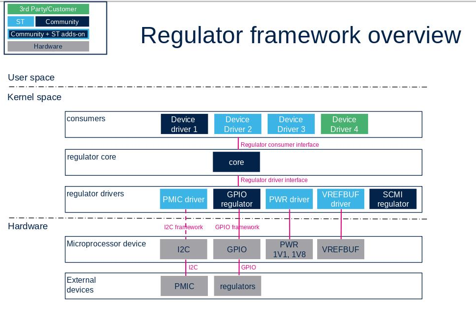
From client application to hardware
- Regulator consumers (Kernel Space): The devices correspond to internal or external peripherals of the microprocessor device ( ADC, SDCARD, USB, ETHERNET... ). Each peripheral that needs a power supply to operate must enable it.
- Regulator framework core (Kernel Space): The core manages all the regulators as described in Linux documentation. A consumer request is not handled directly by a regulator driver. It is handled by the core that can arbitrate requests between consumers in order to save power.
- Regulator drivers (Kernel Space): A regulator that can be controlled (enable/disable, adjust voltage...) needs a driver to operate. This is the role of the regulator driver. A driver can also send notifications like over current or over temperature. SCMI provide accesses to regulators that are not handled in Linux.
- Microprocessor device internal regulators (Hardware): This corresponds to the regulators integrated to the microprocessor device. Those regulators supply mainly the USB and ADC peripherals provided by PWR and VREFBUF.
- External devices (Hardware): external regulators. This corresponds to physical components that provide the various power supplies on the board, for example STMicrolectronics PMIC or GPIO controlled regulator.
Notes:
- The kernel contains generic drivers for GPIO controlled regulators.
- The internal regulators of the microprocessor device are implemented in the STM32 machine.
2.2. API description[edit | edit source]
Depending on needs and the caller location (kernel space or user space), several APIs are available to control a regulator:
- User space API: The regulator framework offers a sysfs interface that can be used for monitoring. It is not possible to control a regulator via the sysfs. See documentation defined in Documentation/ABI/testing/sysfs-class-regulator for details.
- Kernel space API:
- The consumer interface allows to control a regulator (enable/disable, set voltage...), and to register to a notification service, see kernel documentation consumer.rst [2]
- The regulator driver API provides API to the regulators driver, see kernel documentation regulator.rst [3]
- Debugfs API: provides only information about regulator configuration, see #How to trace for example.
3. Configuration[edit | edit source]
3.1. Kernel configuration[edit | edit source]
Regulator framework is activated by default in ST deliveries. Nevertheless, if a specific configuration is needed, this section indicates how regulator drivers can be activated/deactivated in the kernel.
Activate regulators driver in kernel configuration with Linux Menuconfig tool: Menuconfig or how to configure kernel
Device Drivers  --->
  [*] Voltage and Current Regulator Support  --->
    [ ]   Regulator debug support
    <*>   Fixed voltage regulator support
    <*>   Regulator protection consumer
    < >   Virtual regulator consumer support
    < >   Userspace regulator consumer support
   ....
    <*>   SCMI based regulator driver
   ....
    <M>   STMicroelectronics STM32 BOOSTER
    <M>   STMicroelectronics STM32 VREFBUF
    [*]   STMicroelectronics STM32 PWR
    <*>   STMicroelectronics STPMIC1 PMIC Regulators
   ...
Regulators framework supports several drivers. User can select from there any driver among the supported devices; please refer to SCMI overview, PMIC_hardware_components or Linux driver articles for each peripheral.
3.2. Device tree configuration[edit | edit source]
Binding documentation: regulator.yaml
The device tree describes regulators and consumers:
- A regulator provides a supply.
- A consumer uses a supply.
When possible, the supply name comes from the electrical schematics of the board.
The regulator framework also handles the power management.
- Runtime: The consumers should disable the regulators that are not needed and the core disables a regulator as soon as it is not requested by any consumer.
This can be avoided by the usage of regulator-always-on property in the device-tree.
- Suspend : The regulator framework offers the possibility to define suspend states for regulators. This is only possible if the driver allows it.
The regulator suspend sate is no more handled by the linux kernel in OpenSTLinux distribution.
regulator-state-standby, regulator-state-mem, regulator-state-disk are used to define the state of the regulators during suspend.
               regulator-state-standby {
                   regulator-on-in-suspend;
                   regulator-suspend-microvolt = <900000>;
                   regulator-mode = <8>;
               };
               regulator-state-mem {
                   regulator-off-in-suspend;
               };
- The regulator runtime strategy does not apply to suspend. With "regulator-on-in-suspend", the regulator is enabled in suspend even if no consumer uses it.
- "regulator-always-on" does not apply to suspend states.
4. How to use framework[edit | edit source]
4.1. How to define regulator in device tree[edit | edit source]
The regulators have generic parameters defined in the binding documentation: regulator.yaml .
All these device tree properties are managed by Linux kernel framework and are some of them are also supported in other OpenSTLinux components:
- in TF-A and in OP-TEE: regulator-always-on, regulator-enable-ramp-delay
- in OP-TEE: regulator-ramp-delay, regulator-min-microvolt, regulator-max-microvolt
4.1.1. Fixed regulator[edit | edit source]
usb otg vbus:
   vbus_otg: regulator-vbus_otg {
       compatible = "regulator-fixed";
       regulator-name = "vbus_otg";
       regulator-min-microvolt = <5000000>;
       regulator-max-microvolt = <5000000>;
       gpio = <&gpioz 4 0>;
       enable-active-high;
   };
Binding documentation:fixed-regulator.yaml
4.1.2. Gpio controlled regulator[edit | edit source]
sdcard level shifter:
   sd_switch: regulator-sd_switch {
       compatible = "regulator-gpio";
       regulator-name = "sd_switch";
       regulator-min-microvolt = <1800000>;
       regulator-max-microvolt = <2900000>;
       regulator-type = "voltage";
       regulator-always-on;

       gpios = <&gpiof 14 GPIO_ACTIVE_HIGH>;
       gpios-states = <0>;
       states = <1800000 0x1 2900000 0x0>;
   };
Binding documentation:gpio-regulator.yaml
4.1.3. PMIC[edit | edit source]
   pmic: stpmu1@33 {
       compatible = "st,stpmu1";
       reg = <0x33>;
       interrupts = <0 2>;
       interrupt-parent = <&gpioa>;
       interrupt-controller;
       #interrupt-cells = <2>;
       status = "okay";

       regulators {
           compatible = "st,stpmu1-regulators";

           vddcore: buck1 {
               regulator-compatible = "buck1";
               regulator-name = "vddcore";
               regulator-min-microvolt = <800000>;
               regulator-max-microvolt = <1350000>;
               regulator-always-on;
               regulator-initial-mode = <2>;
           };

           vdd_ddr: buck2 {
               regulator-compatible = "buck2";
               regulator-name = "vdd_ddr";
               regulator-min-microvolt = <1350000>;
               regulator-max-microvolt = <1350000>;
               regulator-always-on;
               regulator-initial-mode = <2>;
           };
           ...
       };
Binding documentation:st,stpmic1.yaml
It is the default configuration for STM32MP15x lines ![]() on STMicroelectronics boards, as the PMIC driver is not handled in OP-TEE and the I2C bus isn't secured.
on STMicroelectronics boards, as the PMIC driver is not handled in OP-TEE and the I2C bus isn't secured.
4.1.4. Microprocessor device internal regulator[edit | edit source]
VREFBUF regulator:
   vrefbuf: vrefbuf@50025000 {
       compatible = "st,stm32-vrefbuf";
       reg = <0x50025000 0x8>;
       regulator-min-microvolt = <1500000>;
       regulator-max-microvolt = <2500000>;
       clocks = <&rcc_clk VREF>;
       status = "disabled";
   };
Binding documentation:st,stm32-vrefbuf.yaml
4.1.5. SCMI regulator[edit | edit source]
The SCMI protocol permits to drive a regulator handled by the secure monitor (OP-TEE). Linux scmi driver implements requests like get, set voltage, enable and disable. OP-TEE then receives and arbitrate the requests depending on internal constraints.
On STM32MP15x lines ![]() , this part is not applicable because the regulators are handled by Linux on STMicroelectronics boards for the default configuration; the I2C is not secured and the PMIC is managed by the non secure world.
, this part is not applicable because the regulators are handled by Linux on STMicroelectronics boards for the default configuration; the I2C is not secured and the PMIC is managed by the non secure world.
 scmi0_voltd: protocol@17 {
 	reg = <0x17>;

 	scmi0_regu: regulators {
 		scmi_reg11: voltd-reg11 {
 			voltd-name = "reg11";
 			regulator-name = "reg11";
 		};
 		scmi_reg18: voltd-reg18 {
 			voltd-name = "reg18";
 			regulator-name = "reg18";
 		};
 		...
 	};
 };
Binding documentation:arm,scmi.yaml
4.2. How to define consumers in device tree[edit | edit source]
See below some examples of consumers.
The SDMMC needs 2 power supply:
   &sdmmc1 {
       vmmc-supply = <&vdd_sd>;
       vqmmc-supply = <&sd_switch>;
   };
The name before "-supply" is not free. vmmc and vqmmc are imposed by the consumer driver. They should be aligned with the name used in the data sheet of the driven component.
The USBPHY is supplied by vdd_usb:
   &usbphyc {
       vdd-supply = <&vdd_usb>;
   };
The DAC is supplied by vdda:
   &dac {
       pinctrl-names = "default";
       pinctrl-0 = <&dac_ch1_pins &dac_ch2_pins>;
       vref-supply = <&vdda>;
       status = "okay";
       ...
   };
The regulators can be consumers. This is used to define power domains:
   pmic: stpmu1@33 {
       compatible = "st,stpmu1";
       ...

       regulators {
           compatible = "st,stpmu1-regulators";

           ldo1-supply = <&v3v3>;
           ldo2-supply = <&v3v3>;
           ldo5-supply = <&v3v3>;
           ldo6-supply = <&v3v3>;
           vref_ddr-supply = <&vdd_ddr>;
           vbus_otg-supply = <&bst_out>;
           sw_out-supply = <&bst_out>;
           ...
       };
   };
Enabling ldo1 will enable v3v3 automatically.
5. How to trace and debug the framework[edit | edit source]
5.1. How to trace[edit | edit source]
The regulator framework provides debugfs tools. The most important one is regulator/regulator_summary:
cat /sys/kernel/debug/regulator/regulator_summary
 regulator                      use open bypass voltage current     min     max
 -------------------------------------------------------------------------------
  regulator-dummy                  0    6      0     0mV     0mA     0mV     0mV
     vddcore                       0    0      0  1200mV     0mA   800mV  1350mV
     vdd_ddr                       0    1      0  1350mV     0mA  1350mV  1350mV
        vtt_ddr                    0    0      0   675mV     0mA   675mV   675mV
     vdd                           0    1      0  3300mV     0mA  3300mV  3300mV
        58007000.sdmmc                                            3300mV  3300mV
     v3v3                          1    5      0  3300mV     0mA  3300mV  3300mV
        58007000.sdmmc                                            3300mV  3300mV
        vdda                       0    2      0  2900mV     0mA  2900mV  2900mV
           40017000.dac                                              0mV     0mV
           48003000.adc                                              0mV     0mV
        v2v8                       0    0      0  2800mV     0mA  2800mV  2800mV
        vdd_sd                     0    1      0  2900mV     0mA  2900mV  2900mV
           58005000.sdmmc                                         2900mV  2900mV
        v1v8                       0    0      0  1800mV     0mA  1800mV  1800mV
     vdd_usb                       0    0      0  3300mV     0mA  3300mV  3300mV
     bst_out                       0    2      0  5000mV     0mA     0mV     0mV
        vbus_otg                   0    0      0  5000mV     0mA     0mV     0mV
        vbus_sw                    0    0      0  5000mV     0mA     0mV     0mV
  sd_switch                        0    1      0  2900mV     0mA  1800mV  2900mV
     58005000.sdmmc                                               2700mV  2900mV
  reg11                            0    0      0  1100mV     0mA  1100mV  1100mV
  reg18                            0    0      0  1800mV     0mA  1800mV  1800mV
  usb33                            0    0      0  3300mV     0mA  3300mV  3300mV
  vref_ddr                         0    0      0   675mV     0mA     0mV     0mV
Notes:
- use: counts the "enable" calls made by the consumers
- open: is the number of consumers that get the regulator
- vdd_sd is a consumer for v3v3
- 58005000.sdmmc is a consumer for v3v3, vdd_sd, sd_switch
- when regulator_always_on property is set, use is equal to ZERO (but the regulator is enabled...)
To help the usage of SCMI regulators, linux can request OP-TEE to print the regulators status with xtest tool:
xtest --stats --regulators
I/TC: Regulator tree summary
I/TC: o- vpp_ddr 	(on  / refcnt 1 / flags 0x1 / 2500 mV fixed)
I/TC: o- vdd3v3_usb 	(on  / refcnt 1 / flags 0x1 / 3300 mV fixed)
I/TC: o- vtt_ddr 	(on  / refcnt 1 / flags 0x1 / 900 mV [0 V .. MAX])
I/TC: o- vdd_sdcard 	(on  / refcnt 1 / flags 0x1 / 3300 mV fixed)
I/TC:    `-- vddio_sdcard 	(on  / refcnt 1 / flags 0 / 1800 mV [1800 mV .. 3300 mV])
I/TC:        `-- vddio1 	(on  / refcnt 1 / flags 0 / 1800 mV [1800 mV .. 3300 mV])
I/TC: o- vdda1v8_aon 	(on  / refcnt 1 / flags 0x1 / 1800 mV fixed)
I/TC: o- v3v3 	(on  / refcnt 1 / flags 0x1 / 3300 mV fixed)
I/TC: o- vdd_ddr 	(on  / refcnt 1 / flags 0x1 / 1200 mV fixed)
I/TC: o- v1v8 	(on  / refcnt 1 / flags 0x1 / 1800 mV fixed)
I/TC:    `-- vdda18adc 	(on  / refcnt 1 / flags 0x1 / 1800 mV fixed)
I/TC: o- vddio_pmic 	(on  / refcnt 1 / flags 0x1 / 3300 mV fixed)
I/TC:    |-- vddio 	(on  / refcnt 1 / flags 0x1 / 3300 mV [0 V .. MAX])
I/TC:    |-- vddio3 	(on  / refcnt 1 / flags 0x1 / 3300 mV [0 V .. MAX])
I/TC:    `-- vddio2 	(on  / refcnt 1 / flags 0x1 / 3300 mV [0 V .. MAX])
I/TC: o- vddcore 	(on  / refcnt 1 / flags 0x1 / 820 mV fixed)
I/TC: o- vddcpu 	(on  / refcnt 1 / flags 0x1 / 800 mV [800 mV .. 910 mV])
6. Source code location[edit | edit source]
The regulator source files are located inside the Linux kernel.
- Framework core: drivers/regulator/ core.c
- Drivers: drivers/regulator/
- Driver interface: include/linux/regulator/driver.h
- Consumer interface: include/linux/regulator/consumer.h
7. References[edit | edit source]
- ↑ kernel documentation overview: Documentation/power/regulator/overview.rst
- ↑ Consumer API documentation: Documentation/power/regulator/consumer.rst
- ↑ Driver API documentation: Documentation/power/regulator/regulator.rst