Template:ArticleBasedOnModel Template:ArticleMainWriter Template:ArticleApprovedVersion
1. Article purpose[edit | edit source]
The inter-processor communication controller (IPCC) is used to exchange data between two processors. It provides a non blocking signaling mechanism to post and retrieve information in an atomic way. Note that shared memory buffers are allocated in the MCU SRAM, which is not part of the IPCC block.
2. Peripheral overview[edit | edit source]
The IPCC peripheral provides a hardware support to manage inter-processor communication between two processor instances. Each processor owns specific register bank and interrupts.
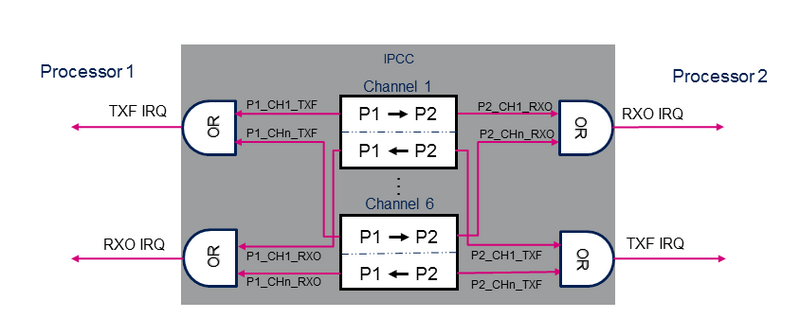
The IPCC provides the signaling for six bidirectional channels.
Each channel is divided into two subchannels that offer a unidirectional signaling from the "sender" processor to the "receiver" processor:
- P1_TO_P2 subchannel
- P2_TO_P1 subchannel
A subchannel consists in:
- One flag that toggles between occupied and free: the flag is set to occupied by the "sender" processor and cleared by the "receiver" processor.
- Two associated interrupts (shared with the other channels):
- RXO: RX channel occupied, connected to the "receiver" processor.
- TXF: TX channel free, connected to the "sender" processor.
- Two associated interrupt masks multiplexing channel IRQs.

The IPCC supports the following channel operating modes:
- Simplex communication mode:
- Only one subchannel is used.
- Unidirectional messages: once the "sender" processor has posted the communication data in the memory, it sets the channel status flag to occupied. The "receiver" processor clears the flag when the message is treated.
- Half-duplex communication mode:
- Only one subchannel is used.
- Bidirectional messages: once the "sender" processor has posted the communication data in the memory, it sets the channel status flag to occupied. The "receiver" processor clears the flag when the message is treated and the response is available in shared memory.
- Full-duplex communication mode:
- The subchannels are used in Asynchronous mode.
- Any processor can post asynchronously a message by setting the subchannel status flag to occupied. The "receiver" processor clears the flag when the message is treated. This mode can be considered as a combination of two simplex modes on a given channel.
2.1. Features[edit | edit source]
Refer to STM32MP15 reference manuals for the complete features list, and to the software components, introduced below, to see which features are implemented.
2.2. Security support[edit | edit source]
The IPCC is a non-secure peripheral.
3. Peripheral usage and associated software[edit | edit source]
3.1. Boot time[edit | edit source]
The IPCC is not used at boot time.
3.2. Runtime[edit | edit source]
3.2.1. Overview[edit | edit source]
STMicroelectronics distribution uses the IPCC peripheral for inter-processor communication with the following configuration:
- IPCC processor 1 interface is assigned to Arm® Cortex®-A7 non-secure context and handled by Linux mailbox framework.
- IPCC processor 2 interface is assigned to Arm® Cortex®-M4 context and handled by the IPCC HAL driver.
3.2.2. Software frameworks[edit | edit source]
| Domain | Peripheral | Software frameworks | Comment | ||
| Cortex-A7 S (OP-TEE) |
Cortex-A7 NS (Linux) |
Cortex-M4 (STM32Cube) | |||
| Coprocessor | IPCC | Linux mailbox framework | STM32Cube IPCC driver | ||
3.2.3. Peripheral configuration[edit | edit source]
The configuration is applied by the firmware running in the context to which the peripheral is assigned. The configuration can be done alone via the STM32CubeMX tool for all internal peripherals, and then manually completed (particularly for external peripherals) according to the information given in the corresponding software framework article.
The IPCC peripheral is shared between the Arm Cortex-A and Cortex-M contexts. A particular attention must therefore be paid to have a complementary configuration on both contexts. In STMicroelectronics distribution, the IPCC is configured as described below. To ensure the coherency of the system, it is recommended to keep this configuration unchanged in your implementation.
- Processor interface
| Processor interface | Context | ||
| Cortex-A7 NS (Linux) |
Cortex-M4 (STM32Cube) | ||
| Processor 1 interface | ☑ | ☐ | |
| Processor 2 interface | ☐ | ☑ | |
- Channel allocation
| Channel | Mode | Usage | Software client frameworks | ||
| Cortex-A7 NS (Linux) |
Cortex-M4 (STM32Cube) | ||||
| Channel 1 | Full-duplex communication | RPMsg transfer from Cortex-M to Cortex-A
|
RPMsg framework | OpenAMP | |
| Channel 2 | Full-duplex communication | RPMsg transfer from Cortex-A to Cortex-M
|
RPmsg framework | OpenAMP | |
| Channel 3 | Simplex communication | Cortex-M4 shutdown request | RemoteProc framework | CprocSync cube utility | |
| Channel 4 | free | ||||
| Channel 5 | free | ||||
| Channel 6 | free | ||||
3.2.4. Peripheral assignment[edit | edit source]
It does not make sense to allocate the IPCC to a single runtime execution context. It is consequently enabled by default for both cores in the STM32CubeMX.
Check boxes illustrate the possible peripheral allocations supported by STM32 MPU Embedded Software:
- ☐ means that the peripheral can be assigned (☑) to the given runtime context.
- ✓ is used for system peripherals that cannot be unchecked because they are statically connected in the device.
Refer to How to assign an internal peripheral to a runtime context for more information on how to assign peripherals manually or via STM32CubeMX.
The present chapter describes STMicroelectronics recommendations or choice of implementation. Additional possiblities might be described in STM32MP15 reference manuals.
| Domain | Peripheral | Runtime allocation | Comment | |||
| Instance | Cortex-A7 S (OP-TEE) |
Cortex-A7 NS (Linux) |
Cortex-M4 (STM32Cube) | |||
| Coprocessor | IPCC | IPCC | ☑ | ☑ | Shared (none or both) | |
