Target description
1. Introduction
The secure boot is the first firmware executed after a reset and verifies the integrity of the user application(s) (check if not modified) before executing it.
It also ensures a secure firmware installation and firmware update. The integrity and authentication (identity) of the user application image(s) are verified before installation.
It also activates the security mechanisms.
This is called the Root of Trust (RoT).
2. Secure Boot stages
The secure boot can be done in one or two stages.
The first stage is done by an immutable code (iRoT). It can't be modified and must include only the mandatory services.
In the second stage (optional), more complex operations can be done. It can be updated in case of future required improvements (e.g. attack robustness improvements).
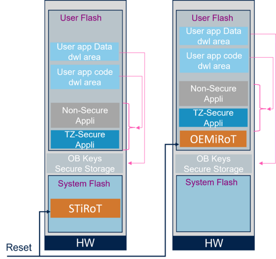
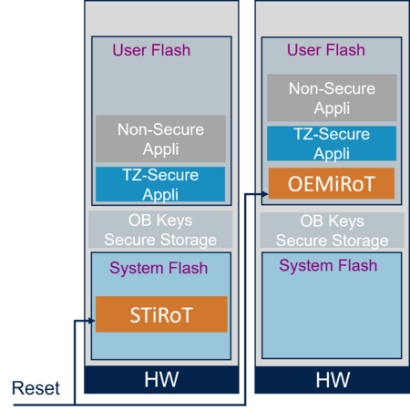
First stage: Two Immutable Root of Trust (iRoT) are possible for the STM32H5.
- The STiRoT: Immutable code, provided by ST and integrated into the system flash of the devices supporting embedded cryptographic accelerator.
- The OEMiRoT: An OEM can develop his boot code including a similar feature to STiRoT. Flash write protection is used to ensure this code cannot be modified (immutable).
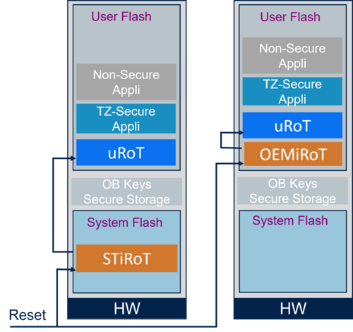
Second optional stage: Two updatable Root of Trust (uRoT) are possible for the STM32H5.
- STuRoT: installable service provided by ST, includes module installation/update capability
- OEMuRoT: developed by 3rd party OEM and installed through the embedded bootloader
As mentioned above, the uRoT has the advantage to be updatable for later modifications or improvements.
2.1. One secure boot stage
Two possible single-stage boots are possible:
- STiRoT using the immutable firmware provided by ST and natively embedded in the device
- OEMiRoT immutable firmware developed and installed by an OEM.
Two possible use cases for STiRoT or OEMiRoT:
Case 1:
A new firmware image (encrypted and signed image containing the secure and the non-secure applications) or a new data image (encrypted and signed image) needs to be installed.
- The iRoT verifies the integrity and authentication of the image (placed in a user flash download area).
- For a user firmware: the image is decrypted and installed in the defined execution user flash area.
- For user data, if applicable, the image is decrypted and stored after re-encryption in a secure storage area (refer to Security features on STM32H5 MCUs article).
Case 2:
A secure user application and if applicable non-secure user application is already installed in the user flash.
- The iRoT verifies the integrity before the user firmware execution, so it ensures that this firmware has not been modified.
2.2. Two secure boot stages
For two secure boot stages first the iRoT is executed followed by the uRoT.
- Role of the iRoT (STiRoT or OEMiRoT):
- The iRoT ensures the secure installation of the uRoT through verification of the integrity and authenticity of the uRoT firmware.
- The iRoT verifies the integrity of the uRoT before executing the uRoT firmware.
- The iRoT is only insuring the secure execution of the next boot stage (uRoT)
- Role of the uRoT (STuRoT or OEMuRoT)
- The uRoT verifies the integrity and authentication of the user application firmware images (secure and non-secure) and the user data image (if applicable) before installing it.
- The uRoT verifies the integrity of the user application firmware (secure and non-secure) before allowing the execution.
3. State after reset and Isolation levels
A secure boot is guaranteed through the isolation levels (HDPL).
The HDPL levels are related to customer use cases requiring security.
So, a user does not need to take care of the HDPL level if no iRoT and uRoT (optional) are used with a product in the OPEN state (refer to Introduction to Silicon device life cycle article
- The HDPL is controlled through a protected hardware block SBS (System Boot and Security).
- The HDPL level is defined by a monotonic counter, incremented during the boot stages.
- A power-on or system reset is needed to reset the HDPL counter.
- The access and execution rights are defined for each isolation level.
- At a specific HDPL level, the code and related secrets of the previous HDPL levels can't be accessed.
- Level 0 (HDPL0): never erased, reserved for system flash memory
- The RSS (Root Security Service) includes
- The RSSFS (Root Security Service First Stage) is embedded in the system flash. It is an immutable code programmed by ST.
- The RSSe (RSS extension) is loaded and installed in SRAM.
- When the device is in PROVISIONING product state and the TrustZone® is enabled, the boot of the device is automatically forced through the RSS
- The RSS is used to install securely an extension (for instance allowing the provisioning of a device)
- The RSS (Root Security Service) includes
- Level 1 (HDPL1): immutable Root of Trust, iRoT: STiRoT (embedded natively in system flash, fixed and never erased) or OEMiRoT (user flash, installed by OEM)
- Level 2 (HDPL2): updatable Root of Trust, uRoT, further optional boot stage: OEMuRoT (user flash, installed by OEM) or STuRoT (installable service provided by ST)
- Level 3 (HDPL3): secure user application code (protected through TrustZone®), non-secure user application code
- If the uRoT is not present, the STiRoT/OEMiRoT directly calls the secure application. In this case, the user application can be in HDPL2 or HDPL3
Notes:
- For one stage secure boot (no uRoT), the user can choose to execute the user application(s) in HDPL2 or HDPL3. In HDPL2 a debug authentication is needed to access the code as soon as the device is in another state than OPEN. In HDPL3, the debugger stays open for the non-secure application in PROVISIONING, PROVISIONED, and in TZ-Closed states (refer to Debug Authentication article and Product life-cycle phases table in RM0481 and RM0492). So the HDPL3 gives a higher flexibility for debugging a user application(s) under development.
- For the STM32CubeFW examples without a secure boot stage (no iRoT and no uRoT), the user application is running by default in HDPL1. In this case, for a product state different than OPEN, a debug authentication is needed to access the debugger (refer to Debug Authentication for STM32H5 article).
4. The different possible boot paths depending on the STM32H5 series
This section explains the possible boot paths and the limitations, depending on the product series.
Some devices do not support embedded hardware cryptography or the Trust Zone.
- The STM32H533 and STM32H57 support TrustZone® and hardware cryptography, so all boot paths are possible with this device
- The STM32H523 and STM32H56 support TrustZone® but not the hardware cryptography (without export control constraints), so the STiRoT (ST immutable Root of Trust) and the secure manager are not supported.
- The STM32H503 is not supporting TrustZone® and not supporting hardware cryptography (without export control constraints), limiting the possible use cases as explained in the next sections.
The boot path is selected through option bytes programming, as explained in the next sections.
For explanations about the secure manager, please refer to the following articles:
- Architecture description: Secure Manager
- Introduction to the how-to hands-on: Secure Manager STM32H5 How to Intro
4.1. STM32H533 and STM32H573 Boot paths
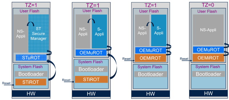
The STM32H533 and STM32H573 series supports services embedded in the system flash (RSS, STiRoT), services developed by an OEM (OEMiRoT, OEMuRoT), and services provided by ST that can be installed (STuRoT, ST-SecureManager).
The embedded hardware cryptography accelerator is used for integrity and authentication verification.
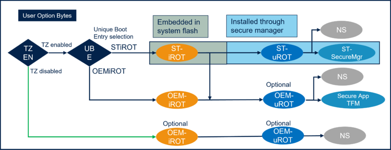
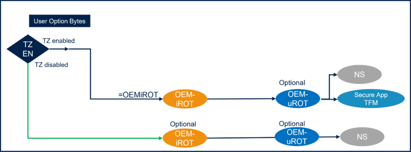
The figure below shows the possible boot paths selected through the related user option bytes.
- When TrustZone® is enabled (TZEN) the Unique Boot Entry (UBE) is selecting which secure boot is executed after reset (STiRoT or OEMiRoT).
- This figure shows also the optional Updatable Root Of Trust (uRoT), which is a second possible boot stage.
The figure below gives another view of some possible boot paths for the STM32H53 and STM32H57 series.
- When TrustZone® is enabled:
- If STiRoT is selected (UBE=0xC3): the STiRoT embedded firmware located in the system flash is executed after reset.
- If OEMiRoT is selected (UBE=0xB4): the OEMiRoT located in the user flash is executed after reset. The address is defined by the SECBOOTADD option byte (default value 0x0C00 0000) (refer to RM0481)
- Note: As mentioned in Figure 4, a second boot stage (OEMuRoT) is not mandatory
- When TrustZone® is disabled:
- OEMiRoT located in the user flash is executed after reset. The address is defined by the NSBOOTADD option byte (default value 0x0800 0000).
- Note: As mentioned in Figure 4, OEMiRoT and OEMuRoT are not mandatory, so it's also possible to have only a non-secure user application code.
- Note: When TrustZone® is disabled, it's not possible to have a secure user application code.
4.2. STM32H52x and STM32H56x Boot paths
The STM32H52x and STM32H56x is not supporting the STiRoT and STuRoT because the cryptographic hardware accelerator is not supported.
Without a hardware cryptographic accelerator, authentication and integrity verification are ensured using the middleware cryptographic library.
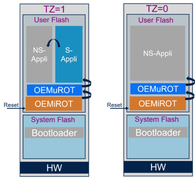
The figure below shows the remaining possible boot paths.
- When TrustZone® is enabled (TZEN) the OEMiRoT is executed after reset.
- This figure shows also the optional Updatable Root of Trust (uRoT), which is a second possible boot stage.
- When TrustZone® is enabled:
- The boot is in the user flash and the address is defined by the SECBOOTADD option byte (default value 0x0C00 0000) (refer to RM0481)
- Note: As mentioned in Figure 6, a second boot stage (OEMuRoT) is not mandatory
- When TrustZone® is disabled:
- The boot is in the user flash and the address is defined by the NSBOOTADD option byte (default value 0x0800 0000)
- Notes:
- As mentioned in Figure 6, OEMiRoT and OEMuRoT are not mandatory, so it's also possible to have only a non-secure user application code.
- When TrustZone® is disabled, it's not possible to have a secure user application code.
- A non-secure user application doesn't mean that it can't be protected. Protection can be done through product state setting (refer to RM0481).
4.3. STM32H50x Boot path
The STM32H50x supports temporal isolation (HDPL) (as for the other STM32H5).
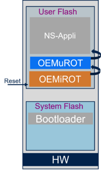
The figure below shows that with STM32H50x the boot can be done through up to three isolated stages.
For STM32H50x, the TrustZone® disabled is the only supported boot path (refer to Figure 5).
A secure user application is not supported since TrustZone® is disabled.
With TrustZone® disabled it's possible to have only a non-secure user application (OEMiRoT and OEMuRoT are optional).
Note: it is possible to protect the non-secure user application by setting the product state (refer to RM0492)
- The Boot is from the user flash and the boot address is defined by the NSBOOTADD (boot address option byte, refer to RM0492)
