1. Introduction
Binding in ZigBee allows an endpoint/cluster identifier pair on one node to be connected to one or more endpoints on other nodes. Instead of sending multiple unicast requests, the application only sends one single request to the Zigbee stack. The binding mechanism is provided by the APS layer, so that the application can set up bindings using binding tables.
Binding is a one way action. Each device has its own binding table.
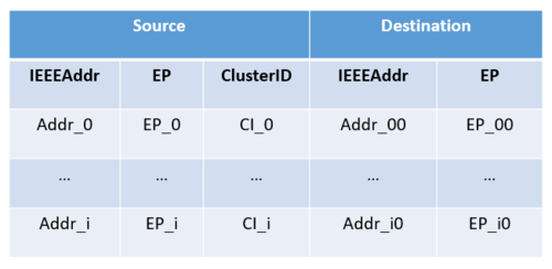
The binding table maps a source address and source endpoint/cluster identifier pair to one or more destination addresses and endpoints.
The BDB provides Find and Bind method to automate the creation of bindings.
| Binding Table Format |
|---|
2. How to configure Binding?
Bindings are pre-configured source-to-destination addresses. They can be configured either locally or remotely. Local binding is typically to be used for client cluster commands. Remote binding is to be typically used for attribute reporting.
2.1. Local configuration
Bindings must be configured in the binding table using the ZbApsmeBindReq().
ZbApsmeBindReq parameter is set as follows:
- srcExtAddr: local client Extended Address
- dst.extAddr: remote server Extended Address
The prototype of the API is :
void ZbApsmeBindReq(struct ZigBeeT *zb, ZbApsmeBindReqT *bindReqPtr, ZbApsmeBindConfT *bindConfPtr);
Parameters:
- zb : Zigbee stack structure
- bindReqPtr : APSME-BIND.request
- bindConfPtr : APSME-BIND.confirm
Here is a code example that utilizes the ZbApsmeBindReq API.
 struct ZbApsmeBindReqT bindreq;
 struct ZbApsmeBindConfT bindconf;

 bindreq.srcExtAddr = xx;
 bindreq.srcEndpt = yy;
 bindreq.clusterId = cluster_id;
 bindreq.dst.mode = ZB_APSDE_ADDRMODE_EXT;
 bindreq.dst.endpoint = endpoint;
 bindreq.dst.extAddr = zz;

 ZbApsmeBindReq(zb,&bindreq,&bindconf);

 if(bindconf.status != ZB_WPAN_STATUS_SUCCESS)
 {
        APP_DBG("Local Bind failed .\n");
 }

 APP_DBG("Binding the client with ext_addr = %#08llx dest endpoint: %d.\n", bindreq.dst.extAddr, bindreq.dst.endpoint);
2.2. Remote configuration
Bindings may also be configured from a remote node using the ZbZdoBindReq().
ZbZdoBindReq parameter is set as follows:
- srcExtAddr: remote server Extended Address
- dst.extAddr: client Extended Address
- target: remote server Short Address
3. Find and Bind
The finding and binding mechanism is a semi-automated method to create bindings. It can be triggered automatically if the bdbCommissioningMode is set to BDB_COMMISSION_MODE_FIND_BIND. However, finding and binding can be started manually from the application by calling ZbStartupFindBindStart() on all endpoints, or calling ZbStartupFindBindStartEndpoint() from a specific endpoint.
Remote binding is only performed for the clusters:
- Alarm
- SE Messaging
- Poll Control
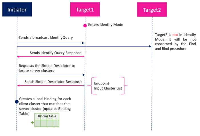
The Find and Bind is based on the Identify cluster. The picture below describes how an initiator (normally client) can create binding with one or more targets (normally server) using the Find and Bind method.
| Find and Bind method |
|---|
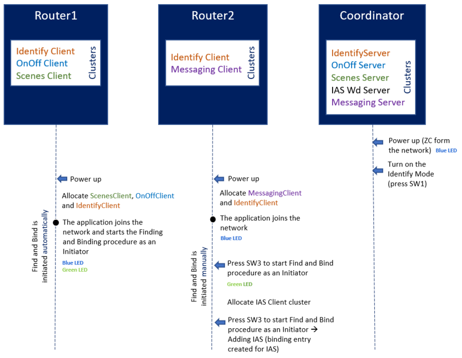
In the example projects provided with STM32CubeWB MCU Package[1], there is an application that describes how to use the Finding and Binding method. The example uses both ways to start Find and Bind: automatic on Router1 (ZR1), and manual on Router2 (ZR2).
As mentioned before, the remote binding is not applicable for all clusters. In this use case, the Router2 has a Messaging cluster client allocated, and so, after starting the Find and Bind procedure, it sends a ZDO Bind Request to the Coordinator (ZC) for the Messaging cluster. The binding entry is added the Coordinator Binding Table.
Local binding is performed for any local client cluster matching the remote server cluster located on the device in identify mode.
As IAS Warning client cluster and Messaging client are located on Router2, and IAS Warning server cluster and Messaging server are located on the Coordinator, the local Binding Table of the Router2 is updated by adding two entries.
| Find and Bind example |
|---|
According to the application setup, the following binding entries should be created:
Remote Binding
- For Messaging cluster between ZC and ZR2
→ Binding entries are added in ZC Binding Table.
Local Binding
- For IAS Warning cluster between ZC and ZR2
- For Messaging cluster between ZC and ZR2
→ Local Binding Table entries are created for the above clusters on the ZR2 side.
- For OnOff cluster between ZC and ZR1
- For Scenes cluster between ZC and ZR1
→ Local Binding Table entries are created for the above clusters on ZR1 side.
4. Attribute Reporting
The ZCL specification allows attribute reporting which configures a Zigbee device to send reports to the requestor, based on the binding table.
Attribute Reporting is often a combination of periodic & event triggered attribute reporting.
The Attribute Report can be sent in a periodic way if the value of the monitored attribute does not change during the Maximum Reporting Interval or the value of the monitored attribute does not change above the reportable change threshold.
If the value of monitored attribute changes above the reportable change, the Attribute Report is immediately sent if no other Attribute Report was sent for at least the Minimum Reporting Interval.
Attribute reporting can be configured on the server in case of default attribute reporting configuration using ZbZclAttrReportConfigDefault, that means, the server sends a default report attribute to all its binding clients with the same configuration. The client can also be configured to ask for a dedicated attribute reporting using ZbZclAttrReportConfigReq, so that the server does not send the default attribute report, and instead sends the requested attribute report.
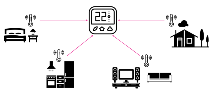
To understand these scenarios, consider a thermostat that needs to keep tracking temperature values. Instead of sending explicit requests to the sensors, the sensors could be configured to send periodically the attribute report to update the temperature values, or to send the attribute report when the temperature reaches the threshold value.
| Thermostat use case |
|---|
Note that:
- Attribute reporting starts after the binding process. The reporting is done from server cluster to client cluster.
- Not all attributes in a cluster are reportable.
5. Acronyms and definitions
| Term | Definition |
|---|---|
| APSME | Application Support Management Entity |
| BDB | Base device behavior |
6. References


