There are four ways to develop an application that is compatible with a secure boot:
- Develop the application without taking into account the secure boot in a first step then adapt the application to the secure boot path. This article explains how to do this.
- Add your code to the ROT template projects (OEMiROT_Appli or STiROT_Appli). These projects have already been adapted to the secure bootpath.
- Update existing ROT applications projects (OEMiROT_Appli or STiROT_Appli). These projects have already been adapted to the secure bootpath.
- Use the STM32CubeMX Boot path functionality. Refer to the how to start with STM32CubeMX and STM32H5 security wiki article.
With STM32H5, several kinds of secure bootpath can be selected. This article is applicable to:
- One boot stage: STiRoT
- One boot stage: OEMiRoT
- Two boot stages: STiRoT + OEMuRoT
This article uses an STM32H573-DK board, but it applies to other STM32H5 boards.
1. Prerequisites
As shown below, STMicroelectronics provide different scripts to facilitate application configuration and firmware image generation.
The application folder structure must match the standard one available in the STM32CubeH5 package, whether it is for a fully secure application or for a secure and nonsecure application. The names of the files and folders underlined in red must be compliant.
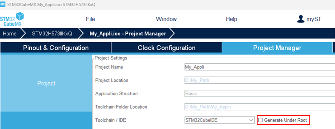
To create this folder structure, when generating the application with STM32CubeMX, ensure that the option "Generate Under Root" is not selected.
2. One boot stage: STiRoT
At reset, STiRoT checks the authenticity and integrity of the user application before executing it. The STiRoT_for_STM32H5 article provides a detailed description of STiRoT.
STiRoT supports the installation of two kinds of application:
- Without isolation: secure-only application. An example is provided in Firmware/Projects/STM32H573-DK/Applications/ROT/STiROT_Appli.
- With isolation: secure and nonsecure applications. An example is provided in Firmware/Projects/STM32H573-DK/Applications/ROT/STiROT_Appli_TrustZone.
When the application runs without secure boot and the user wants to use STiRoT to secure it, follow these steps:
- The memory mapping of the user application must be adapted. The user application booted by STiRoT is always executed in flash memory. The memory mapping of the user application depends on the STiRoT configuration.
- The user application binary must be signed and encrypted. At each boot, STiRoT controls the integrity and authenticity of the user application binary based on TLV added during the image generation.
- Note that a default memory protection unit (MPU) configuration is already applied by STiRoT when jumping to the application. To ensure the security of the device, the MPU is configured to allow execution of the user application code area only. This minimizes the risk of unauthorized code execution. It is the responsibility of the user application to reconfigure the MPU to meet the security requirements.
A set of scripts is available in the Firmware/Projects/STM32H573-DK/ROT_Provisioning folder to activate and configure the STiRoT bootpath. These scripts are designed to adapt the configuration files automatically, such as STiROT_Code_Image.xml and the ob_flash_programming.bat (.sh) script, but also the application linker files based on the STiRoT configuration.
Before executing these scripts, update the stirot_boot_path_project variable in Firmware/Projects/STM32H573-DK/ROT_Provisioning/env.bat (.sh), which must point to the user application folder. As this path is relative from Firmware/Projects/STM32H573-DK it may be necessary to add several "../" (parent directory) to navigate to the drive.
2.1. Application without isolation: STiRoT_Appli example
When an application is designed to run without isolation, it must be 'fully secure'. To meet this requirement, define the project as a secure project:
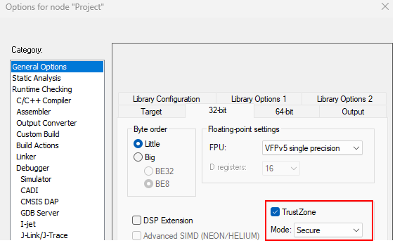
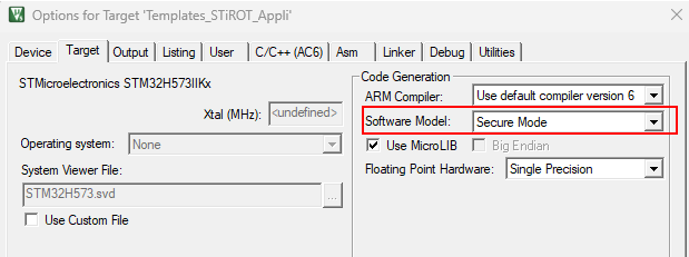
Change nature of your project:
To change the nature of the project, open the .project file with a text editor and replace lines 27 and 28 from the picture below with the new line 27 provided.
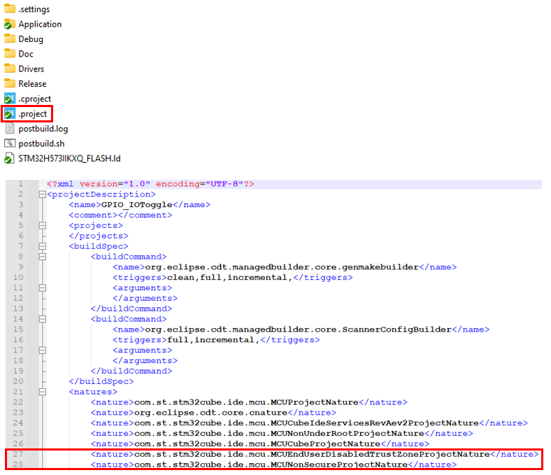
<nature>com.st.stm32cube.ide.mcu.MCUSecureProjectNature</nature>
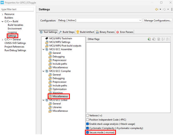
Select the secure compilation option
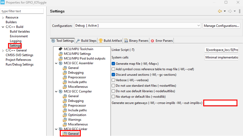
Remove secure gateway generation
2.1.1. User application adaptation
This chapter highlights several parts of the linker file to explain the most important points to consider, but if this file was not modified, it is recommended to use the complete mapping file template provided for STiRoT_Appli and skip the ROM/RAM region adaptation described below.
ROM region adaptation:
When started by STiRoT, the user application is always executed from the flash memory. Moreover, the user application binary must be included in an image including a header, as described in the image generation wiki page. Therefore, the vector table is shifted by 0x400 bytes.
As explained in the Firmware/Projects/STM32H573-DK/Templates/ROT/STiROT_Appli example, the S_CODE_OFFSET, S_CODE_SIZE, and IMAGE_HEADER_SIZE symbols must be added to the linker file. These three symbols are automatically updated during the provisioning process, taking into account the memory configuration of STiROT_Boot. The vector table address and the ROM code section must be defined using the S_CODE_OFFSET, S_CODE_SIZE, and IMAGE_HEADER_SIZE symbols.
Add the code below to the mapping file:

define symbol S_CODE_OFFSET = 0x00000000; /* Firmware execution area offset from STiROT_Config.xml */
define symbol S_CODE_SIZE = 0x00020000; /* Firmware area size from STiROT_Config.xml */
define exported symbol IMAGE_HEADER_SIZE = 0x400; /* mcuboot header size */

define exported symbol __ICFEDIT_intvec_start__ = 0x0C000000 + S_CODE_OFFSET + IMAGE_HEADER_SIZE;
/*-Memory Regions-*/
define exported symbol __ICFEDIT_region_ROM_start__     = 0x0C000000 + S_CODE_OFFSET + IMAGE_HEADER_SIZE;
define symbol __ICFEDIT_region_ROM_end__       = 0x0C000000 + S_CODE_OFFSET + S_CODE_SIZE - 1;

Due to the use of #define, the first line below is also mandatory and must be the first line of the .sct file.
#! armclang --target=arm-arm-none-eabi -march=armv8-m.main -E -xc
#define S_CODE_OFFSET 0x00000000    /* Firmware execution area offset from STiROT_Config.xml */
#define S_CODE_SIZE 0x00020000      /* Firmware area size from STiROT_Config.xml */
#define IMAGE_HEADER_SIZE 0x400     /* mcuboot header size */

#define CODE_START 0x0C000000 + S_CODE_OFFSET + IMAGE_HEADER_SIZE
#define APP_CODE_SIZE S_CODE_SIZE - IMAGE_HEADER_SIZE

S_CODE_OFFSET = 0x00000000;       /* Firmware execution area offset from STiROT_Config.xml */
S_CODE_SIZE = 0x00020000;         /* Firmware area size from STiROT_Config.xml */
IMAGE_HEADER_SIZE = 0x400;       /* mcuboot header size */
MEMORY
{
  RAM    (xrw)    : ORIGIN = 0x30000000,    LENGTH = 0x40000    /* Memory is divided. Actual start is 0x30000000 and actual length is 256K */
  FLASH    (rx)    : ORIGIN = (0xc000000 + S_CODE_OFFSET + IMAGE_HEADER_SIZE),    LENGTH = S_CODE_SIZE - IMAGE_HEADER_SIZE  /* Memory is divided. Actual start is 0x8000000 and actual length is 2048K */
}
RAM region adaptation:
No adaptation is required for STiRoT bootpath.
2.1.2. Image generation
STM32TrustedPackageCreator uses STiRoT_Code_Image.xml (in the Firmware/Projects/STM32H573-DK/ROT_Provisioning/STiROT/Images folder) to generate the image. It contains all required parameters, including the location of the user application binary file (appli.bin). This parameter is automatically updated during the provisioning sequence based on the stirot_boot_path_project variable.
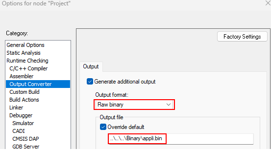
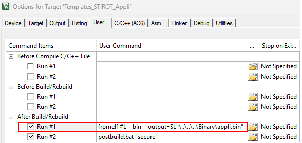
Therefore, the IDE must be configured to generate a .bin file in the My_Appli/Appli/Binary folder (make sure that the correct project tree has been selected).
..\..\..\Binary\appli.binfromelf #L --bin --output=$L"\..\..\..\Binary\appli.bin"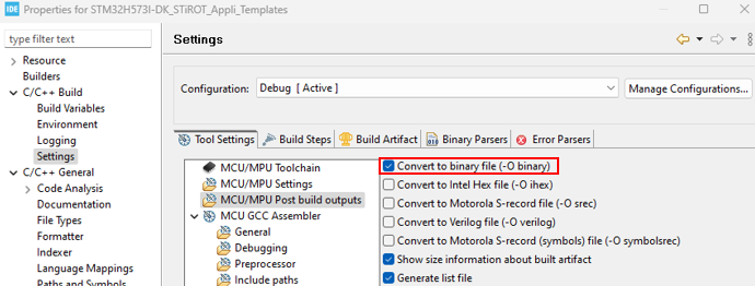
To meet the binary name and location requirements, a postbuild script is implemented to copy the binary file generated by the IDE. This script must be updated with the generated binary name to perform this operation.

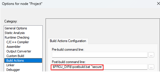
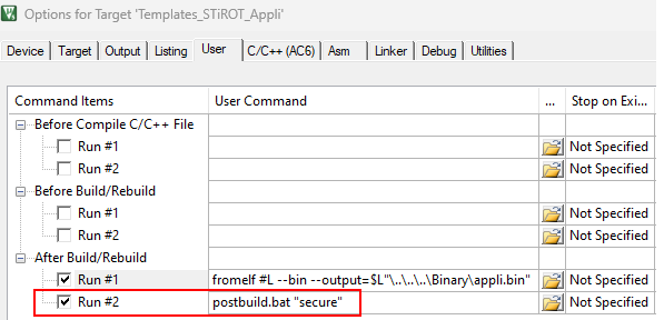
The image generation can be started manually with STM32TrustedPackageCreator, but a more efficient way of working is to modify the user application project to generate the image automatically at the end of each compilation as a postbuild command.
An example of postbuild.bat/.sh is provided in the Firmware/Projects/STM32H573-DK/Templates/ROT/STiROT_Appli and Firmware/Projects/STM32H573-DK/Applications/ROT/STiROT_Appli examples. The image generation is performed based on STiRoT_Code_Image.xml, which is stored in the Firmware/Projects/STM32H573-DK/ROT_Provisioning/STiROT/Images folder. Depending on the location of your application, the postbuild script may be updated to access the STiRoT_Code_Image.xml file.
2.1.3. Security management
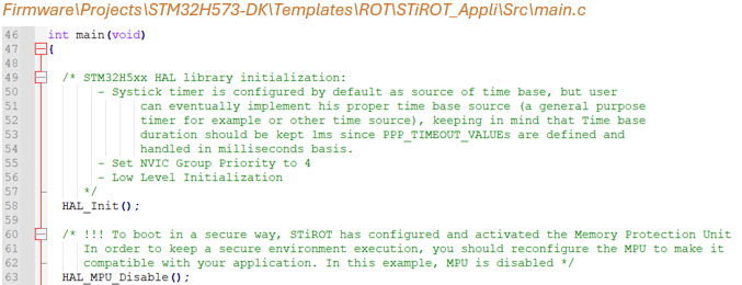
For security robustness, when STiRoT jumps to the user application, the MPU is configured to ensure that only the user application code area can be executed (execution surface controlled via MPU configuration). It is the responsibility of the application to reconfigure the MPU to meet the security requirements.
2.1.4. Miscellaneous
The STiRoT system clock is set to 64, 200, or 250 Mhz by the user through the STiRoT configuration step. The application inherits the STiRoT system clock value if the configuration of the system clock is not updated by the application.
2.1.5. Ready to start
The application has now been adapted to STiRoT Boot path without isolation. To test it, run the provisioning.bat/.sh script stored in the Firmware/Projects/STM32H573-DK/ROT_Provisioning/STiROT folder and follow the instructions.
For more details refer to the Security:How to start with STiRoT on STM32H573#STiRoT and debug authentication configuration wiki page.
2.2. Application with isolation: STiRoT_Appli_TrustZone example
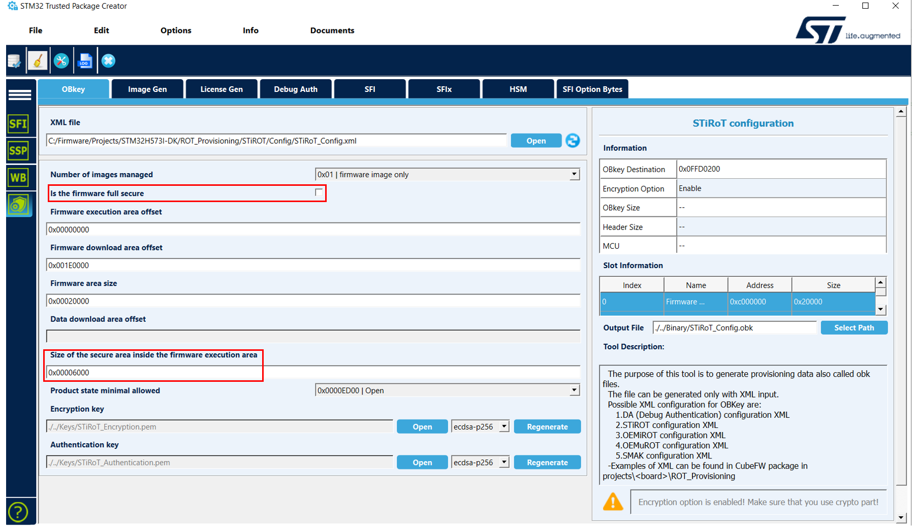
STiRoT_Appli_TrustZone example can be chosen by the user in order to design an application with both a secure and a nonsecure part. For this purpose, update the STiRoT configuration as follows:
- Disable the fully secure image option.
- Update the size of the secure part.
STiRoT_Appli_TrustZone consists of two projects, which must be compiled in a specific order (secure then nonsecure). The image is generated at the end of the nonsecure project compilation.
Before executing these scripts, it is mandatory to update the stirot_boot_path_project variable in Firmware/Projects/STM32H573-DK/ROT_Provisioning/env.bat (.sh), which must point to the user application folder. As this path is relative from Firmware/Projects/STM32H573-DK', it may be necessary to add several "../" (parent directory) to navigate to the drive.
2.2.1. User application adaptation
This chapter highlights several parts of the linker file to explain the most important points to consider, but if this file was not modified, it is recommended to use the complete mapping file template provided for STiRoT_Appli_TrustZone and skip the ROM/RAM region adaptation described below.
ROM region adaptation:
When started by STiRoT, the user application is always executed from the flash memory. Moreover the user application binary must be included in an image including a header, as described in the image generation wiki page. Therefore, the vector table is shifted by 0x400 bytes.
As explained in the Firmware/Projects/STM32H573-DK/Templates/ROT/STiROT_Appli_TrustZone example, the S_CODE_OFFSET, S_CODE_SIZE, NS_CODE_OFFSET, NS_CODE_SIZE, IMAGE_HEADER_SIZE, and CMSE_VENEER_REGION_SIZE symbols must be added to the secure and nonsecure linker files. The vector table address and the ROM code section must be defined using the S_CODE_OFFSET, S_CODE_SIZE, NS_CODE_OFFSET, NS_CODE_SIZE, IMAGE_HEADER_SIZE, and CMSE_VENEER_REGION_SIZE symbols:
IMAGE_HEADER_SIZEis configured by default; do not udpate its value.CMSE VENEER_REGION_SIZEdefines the region used to switch safely between the secure and nonsecure application. It ensures that the transition is controlled and that sensitive data is protected. This value can be configured by the user even if it is recommended to keep the default value.NS_CODE_OFFSETis configured in the examples as the beginning of the area just after the secure area. This value can be updated by the user if they decided to change the partitioning logic.S_CODE_OFFSET,S_CODE_SIZE, andNS_CODE_SIZEare automatically updated during the provisioning process, taking into account the memory configuration of STiRoT.

define exported symbol S_CODE_OFFSET = 0x00000000; /* This define is updated automatically from update_appli_setup.bat/sh */
define exported symbol S_CODE_SIZE = 0x00006000; /* This define is updated automatically from update_appli_setup.bat/sh */
define exported symbol IMAGE_HEADER_SIZE = 0x400; /* mcuboot headre size */
define symbol CMSE_VENEER_REGION_SIZE = 0x400;  /* user configurable */

define exported symbol __ICFEDIT_intvec_start__ = 0x0C000000 + S_CODE_OFFSET + IMAGE_HEADER_SIZE;
/*-Memory Regions-*/
define exported symbol __ICFEDIT_region_ROM_start__     = 0x0C000000 + S_CODE_OFFSET + IMAGE_HEADER_SIZE;
define symbol __ICFEDIT_region_ROM_end__       = 0x0C000000 + S_CODE_OFFSET + S_CODE_SIZE - CMSE_VENEER_REGION_SIZE  - 1;
define symbol __ICFEDIT_region_ROM_NSC_start__ = 0x0C000000 + S_CODE_OFFSET + S_CODE_SIZE - CMSE_VENEER_REGION_SIZE ;
define symbol __ICFEDIT_region_ROM_NSC_end__   = 0x0C000000 + S_CODE_OFFSET + S_CODE_SIZE - 1;
define exported symbol S_CODE_OFFSET =0x00000000; /* This define is updated automatically from update_appli_setup.bat/sh */
define exported symbol S_CODE_SIZE = 0x00006000; /* This define is updated automatically from update_appli_setup.bat/sh */
define exported symbol NS_CODE_OFFSET = S_CODE_OFFSET + S_CODE_SIZE; /* Non secure code Offset */
define exported symbol NS_CODE_SIZE = 0x1A000; /* This define is updated automatically from update_appli_setup.bat/sh */
define exported symbol IMAGE_HEADER_SIZE = 0x400; /* mcuboot headre size */

define exported symbol __ICFEDIT_intvec_start__ = 0x08000000 + NS_CODE_OFFSET + IMAGE_HEADER_SIZE;
/*-Memory Regions-*/
define exported symbol __ICFEDIT_region_ROM_start__     = 0x08000000 + NS_CODE_OFFSET + IMAGE_HEADER_SIZE;
define symbol __ICFEDIT_region_ROM_end__       = 0x08000000 + NS_CODE_OFFSET + NS_CODE_SIZE - 1;

Due to the use of #define, the first line below is also mandatory and must be the first line of the .sct file.
#! armclang --target=arm-arm-none-eabi -march=armv8-m.main -E -xc
#define S_CODE_OFFSET 0x00000000                    /* This define is updated automatically from update_appli_setup.bat/sh */
#define S_CODE_SIZE 0x00006000                      /* This define is updated automatically from update_appli_setup.bat/sh */
#define NS_CODE_OFFSET S_CODE_OFFSET + S_CODE_SIZE  /* Non secure code Offset */
#define IMAGE_HEADER_SIZE 0x400                     /* mcuboot headre size */

#define S_CODE_START 0x0C000000 + S_CODE_OFFSET + IMAGE_HEADER_SIZE
#define S_APP_CODE_SIZE S_CODE_SIZE - CMSE_VENEER_REGION_SIZE - IMAGE_HEADER_SIZE

Due to the use of #define, the first line below is also mandatory and must be the first line of the .sct file.
#! armclang --target=arm-arm-none-eabi -march=armv8-m.main -E -xc
#define S_CODE_OFFSET 0x00000000                       /* This define is updated automatically from update_appli_setup.bat/sh */
#define S_CODE_SIZE 0x00006000                         /* This define is updated automatically from update_appli_setup.bat/sh */

#define NS_CODE_OFFSET S_CODE_OFFSET + S_CODE_SIZE     /* Non secure code Offset */
#define NS_CODE_SIZE 0x1A000                           /* This define is updated automatically from update_appli_setup.bat/sh */

#define IMAGE_HEADER_SIZE 0x400                        /* mcuboot header size */

#define NS_CODE_START 0x08000000 + NS_CODE_OFFSET + IMAGE_HEADER_SIZE
#define NS_APP_CODE_SIZE NS_CODE_SIZE - IMAGE_HEADER_SIZE

S_CODE_OFFSET = 0x00000000;       /* This define is updated automatically from update_appli_setup.bat/sh  */
S_CODE_SIZE = 0x00006000;         /* This define is updated automatically from update_appli_setup.bat/sh  */
IMAGE_HEADER_SIZE = 0x400;       /* mcuboot header size */
CMSE_VENEER_REGION_SIZE = 0x400;  /* user configurable */
MEMORY
{
  RAM    (xrw)    : ORIGIN = 0x30000000,    LENGTH = 0x40000    /* Memory is divided. Actual start is 0x30000000 and actual length is 256K */
  FLASH    (rx)    : ORIGIN = (0xc000000 + S_CODE_OFFSET + IMAGE_HEADER_SIZE),    LENGTH = (S_CODE_SIZE - IMAGE_HEADER_SIZE  - CMSE_VENEER_REGION_SIZE)    /* Memory is divided. Actual start is 0x8000000 and actual length is 2048K */
  FLASH_NSC    (rx)    : ORIGIN = (0xc000000 + S_CODE_OFFSET + S_CODE_SIZE - CMSE_VENEER_REGION_SIZE),    LENGTH = (CMSE_VENEER_REGION_SIZE)    /* Non-Secure Call-able region */
}
S_CODE_OFFSET = 0x00000000;                        /* This define is updated automatically from update_appli_setup.bat/sh */
S_CODE_SIZE = 0x00006000;                           /* This define is updated automatically from update_appli_setup.bat/sh */
NS_CODE_SIZE = 0x1A000;                          /* This define is updated automatically from update_appli_setup.bat/sh */
NS_CODE_OFFSET = (S_CODE_OFFSET + S_CODE_SIZE);
IMAGE_HEADER_SIZE = 0x400;                      /* mcuboot header size */
MEMORY
{
  RAM    (xrw)    : ORIGIN = 0x20050000,    LENGTH = 0x50000    /* Memory is divided. Actual start is 0x20000000 and actual length is 640K */
  FLASH    (rx)    : ORIGIN = (0x08000000 + NS_CODE_OFFSET + IMAGE_HEADER_SIZE),    LENGTH = (NS_CODE_SIZE - IMAGE_HEADER_SIZE)    /* Memory is divided. Actual start is 0x8000000 and actual length is 2048K */
}
RAM region adaptation:
No adaptation is required for STiRoT Boot path. From a partitioning point of view, secure and nonsecure firmware cannot access the same physical area of the SRAM. Therefore, to simplify RAM partitioning, secure code uses SRAM1 (through secure aliases) while nonsecure code uses SRAM3 (through nonsecure aliases).
2.2.2. Image generation
STiRoT_Appli_TrustZone consists of two projects which must be compiled in a specific order (secure then nonsecure). The image is generated at the end of the nonsecure project compilation.
STM32TrustedPackageCreator uses STiRoT_Code_Image.xml (in the Firmware/Projects/STM32H573-DK/ROT_Provisioning/STiROT/Images folder) to generate the image. It contains all required parameters, including the location of the user application binary file (appli.bin). This parameter is automatically updated during the provisioning sequence based on the stirot_boot_path_project variable.
Therefore, the IDE must be configured to generate a .bin file.

..\..\..\..\Binary\appli_s.bin..\..\..\..\Binary\appli_ns.bin
The assembly is performed at the postbuild stage of the nonsecure project.

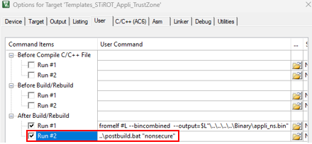
fromelf #L --bincombined --output=$L"\..\..\..\..\Binary\appli_s.bin"fromelf #L --bincombined --output=$L"\..\..\..\..\Binary\appli_ns.bin"
The assembly is performed at the postbuild stage of the nonsecure project.

Nonsecure

The assembly is performed at the postbuild stage of the nonsecure project.
To perform the assembly, the postbuild script must be updated with the generated binary names.

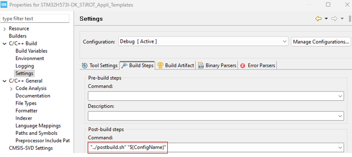
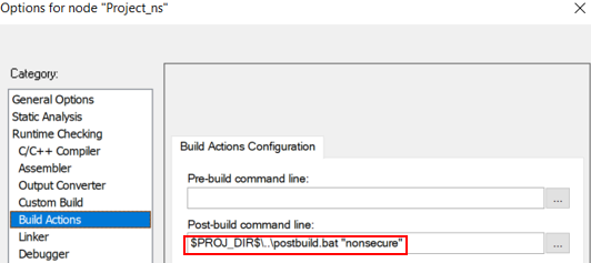
The image generation can be started manually using STM32TrustedPackageCreator but a more efficient way of working is to modify the user application project to generate the image automatically at the end of each compilation as a postbuild command.
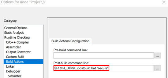
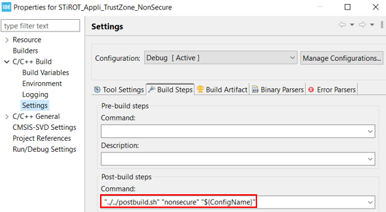
$PROJ_DIR$\..\postbuild.bat "secure"$PROJ_DIR$\..\postbuild.bat "nonsecure"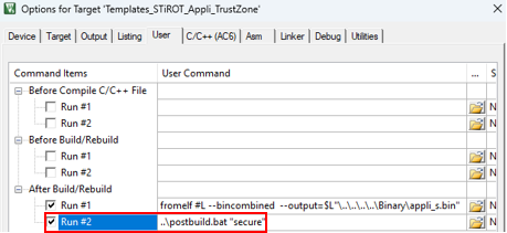
..\postbuild.bat "secure"..\postbuild.bat "nonsecure"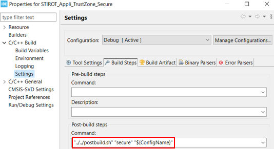
"../../postbuild.sh" "secure" "${ConfigName}""../../postbuild.sh" "nonsecure" "${ConfigName}"
.
An example of postbuild.bat/.sh is provided in the Firmware/Projects/STM32H573-DK/Templates/ROT/STiROT_Appli_TrustZone and Firmware/Projects/STM32H573-DK/Applications/ROT/STiROT_Appli_TrustZone examples. The image generation is performed based on STiRoT_Code_Image.xml, which is stored in the Firmware/Projects/STM32H573-DK/ROT_Provisioning/STiROT/Images folder. Depending on the location of the application, the postbuild script may be updated to access the STiRoT_Code_Image.xml file.
2.2.3. Security management
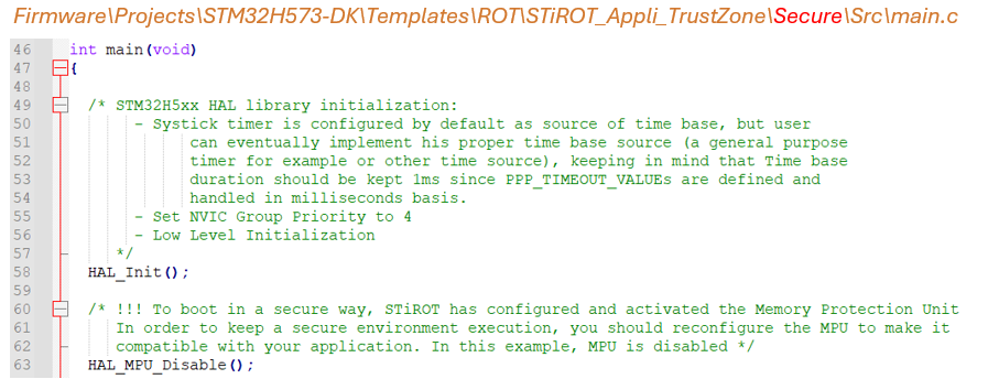
For security robustness, when STiRoT jumps to the user application, the MPU is configured to ensure that only the user application code area can be executed (execution surface controlled via MPU configuration). It is the responsibility of the application to reconfigure the MPU to meet the security requirements.
2.2.4. Miscellaneous
The STiRoT system clock is set to 64, 200, or 250 Mhz by the user through the STiRoT configuration step. The application inherits the STiRoT system clock value if the configuration of the system clock is not updated by the application.
2.2.5. Ready to start
The application has now been adapted to STiRoT Boot path with isolation. To test it, run the provisioning.bat/.sh script stored in the Firmware/Projects/STM32H573-DK/ROT_Provisioning/STiROT folder and follow the instructions.
For more details, refer to the Security:How to start with STiRoT on STM32H573#STiRoT and debug authentication configuration wiki page.
3. One boot stage: OEMiRoT
To use OEMiRoT to secure an application that runs without secure boot, follow these steps:
- Configure OEMiRoT according to your application requirements (such as the number of images or image size).
- The memory mapping of the user application must be adapted, depending on the OEMiRoT configuration.
- The user application binary must be signed and encrypted. At each boot, OEMiRoT controls the integrity and the authenticity of the user application binary based on TLV added during the image generation.
- Be aware that a default MPU configuration is already applied by OEMiRoT when jumping to the application. To ensure the security of the device, the MPU is configured to allow the execution of the user application code area only. This minimizes the risk of unauthorized code execution. It is the responsibility of the user application to reconfigure the MPU to meet the security requirements.
A set of scripts is provided in the Firmware/Projects/STM32H573-DK/ROT_Provisioning folder to activate and configure OEMiRoT Boot path. These scripts are designed to adapt the configuration files automatically, such as OEMiROT_Code_Image.xml and the ob_flash_programming.bat (.sh) script, but also the application linker files based on the OEMiRoT configuration.
Before executing these scripts it is mandatory to update the oemirot_boot_path_project variable in Firmware/Projects/STM32H573-DK/ROT_Provisioning/env.bat (.sh) which must point to the user application folder. As this path is relative from Firmware/Projects/STM32H573-DK, it may be necessary to add several "../" (parent directory) to navigate to the drive.
3.1. OEMiRoT configuration
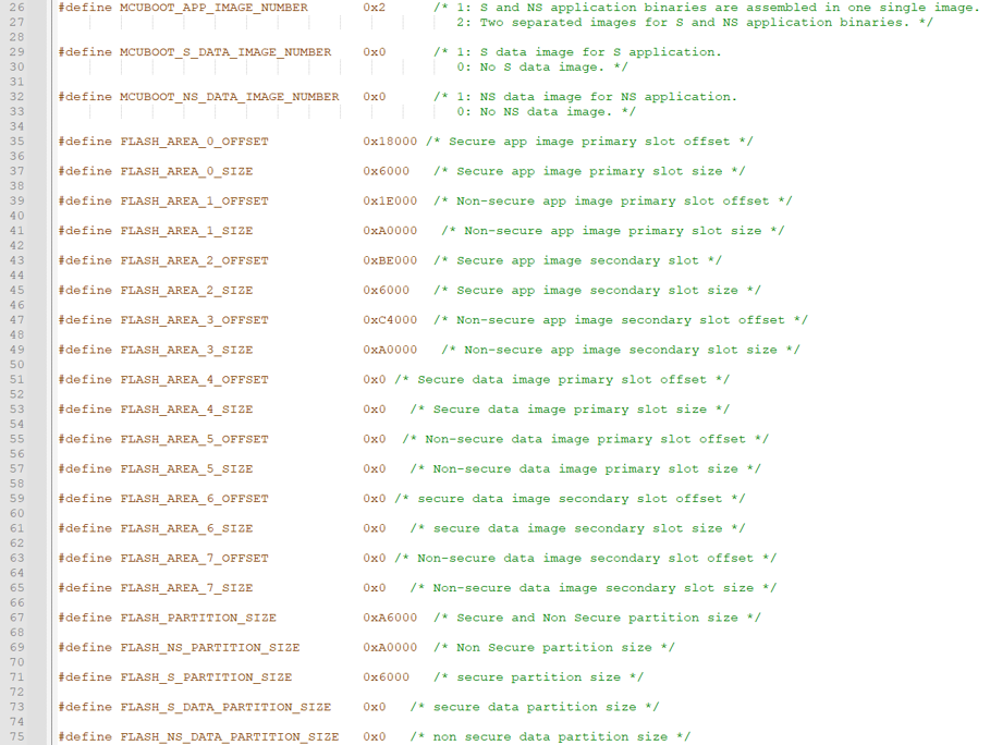
To tailor OEMiRoT to the application requirements, edit the file Firmware/Projects/STM32H573-DK/Applications/ROT/OEMiROT_Boot/Inc/flash_layout.h. The figure below lists several key parameters from this file.
This example uses the default flash memory layout as defined:
- Two separate images for secure and nonsecure application binaries
- No secure data image
- No nonsecure data image
- FLASH_S_PARTITION_SIZE 0x06000
- FLASH_NS_PARTITION_SIZE 0xA0000
- FLASH_S_DATA_PARTITION_SIZE 0x0 (as there is no secure data image)
- FLASH_NS_DATA_PARTITION_SIZE 0x0 (as there is no nonsecure data image)
The OEMiRoT_Boot postbuild command propagates the flash memory layout configuration to the provisioning scripts and application linker files. It can also propagate it automatically to an application header file. It can be useful for the application to use it, especially to know where to program new firmware images in download slot areas.
To benefit from this automatic header file update in the application, copy the file Firmware\Projects\STM32H573I-DK\Applications\ROT\OEMiROT_Appli_TrustZone\Secure_nsclib\appli_flash_layout.h to the application directory My_Appli\Secure_nsclib\appli_flash_layout.h.
3.2. User application adaptation
In this chapter, we will highlight some parts of the linker file to explain the most important points to consider, but if this file was not modified, it is recommended to use the complete mapping file template provided for STiRoT_Appli_TrustZone and skip the ROM/RAM region adaptation described below.
ROM region adaptation:
When started by OEMiRoT, the user application binary must be included in an image including a header, as described in the image generation wiki page. Therefore, the vector table is shifted by 0x400 bytes.
As explained in the Firmware/Projects/STM32H573-DK/Templates/ROT/OEMiROT_Appli_TrustZone example, the S_CODE_OFFSET, S_CODE_SIZE, NS_CODE_OFFSET, NS_CODE_SIZE, IMAGE_HEADER_SIZE, and CMSE_VENEER_REGION_SIZE symbols must be added to the linker files of the secure and nonsecure projects. These symbols are updated automatically during the OEMiROT_Boot project compilation, taking into account the memory configuration of OEMiROT_Boot, which depends on the MCUBOOT_OVERWRITE_ONLY, MCUBOOT_APP_IMAGE_NUMBER, MCUBOOT_S_DATA_IMAGE_NUMBER, and MCUBOOT_NS_DATA_IMAGE_NUMBER compilation switches. The vector table address and the ROM code section must be defined using the S_CODE_OFFSET, S_CODE_SIZE, NS_CODE_OFFSET, NS_CODE_SIZE, IMAGE_HEADER_SIZE, and CMSE_VENEER_REGION_SIZE symbols:
IMAGE_HEADER_SIZEis configured by default; do not update its value.CMSE VENEER_REGION_SIZEdefines the region used to switch safely between the secure and nonsecure application. It ensures that the transition is controlled and that sensitive data is protected. This value can be configured by the user even if it is recommended to keep the default value.NS_CODE_OFFSETis configured in the examples as the beginning of the area just after the secure area. This value can be updated by the user if they decided to change the partitioning logic.S_CODE_OFFSET,S_CODE_SIZE, andNS_CODE_SIZEare updated automatically during the OEMiROT_Boot project compilation.

define exported symbol S_CODE_OFFSET =0x12000; /* This define is updated automatically by OEMiROT_Boot postbuild */
define exported symbol S_CODE_SIZE = 0x6000; /* This define is updated automatically by OEMiROT_Boot postbuild */
define exported symbol NS_CODE_OFFSET = S_CODE_OFFSET + S_CODE_SIZE; /* Non secure code Offset */
define exported symbol IMAGE_HEADER_SIZE = 0x400; /* mcuboot headre size */
define  symbol CMSE_VENEER_REGION_SIZE = 0x400;  /* Include TLVs and trailer. User configurable */

define exported symbol __ICFEDIT_intvec_start__ = 0x0C000000 + S_CODE_OFFSET + IMAGE_HEADER_SIZE;
/*-Memory Regions-*/
define exported symbol __ICFEDIT_region_ROM_start__     = 0x0C000000 + S_CODE_OFFSET + IMAGE_HEADER_SIZE;
define symbol __ICFEDIT_region_ROM_end__       = 0x0C000000 + S_CODE_OFFSET + S_CODE_SIZE - CMSE_VENEER_REGION_SIZE - 1;
define symbol __ICFEDIT_region_ROM_NSC_start__ = 0x0C000000 + S_CODE_OFFSET + S_CODE_SIZE - CMSE_VENEER_REGION_SIZE;
define symbol __ICFEDIT_region_ROM_NSC_end__ = 0x0C000000 + S_CODE_OFFSET + S_CODE_SIZE - 1;
define exported symbol S_CODE_OFFSET = 0x12000; /* This define is updated automatically by OEMiROT_Boot postbuild */
define exported symbol S_CODE_SIZE = 0x6000; /* This define is updated automatically by OEMiROT_Boot postbuild */
define exported symbol NS_CODE_OFFSET = S_CODE_OFFSET + S_CODE_SIZE; /* Non secure code Offset */
define exported symbol NS_CODE_SIZE = 0xA0000; /* This define is updated automatically by OEMiROT_Boot postbuild */
define exported symbol IMAGE_HEADER_SIZE = 0x400; /* mcuboot headre size */

define exported symbol __ICFEDIT_intvec_start__ = 0x08000000 + NS_CODE_OFFSET + IMAGE_HEADER_SIZE;
/*-Memory Regions-*/
define exported symbol __ICFEDIT_region_ROM_start__     = 0x08000000 + NS_CODE_OFFSET + IMAGE_HEADER_SIZE;
define symbol __ICFEDIT_region_ROM_end__       = 0x08000000 + NS_CODE_OFFSET + NS_CODE_SIZE - 1;

Due to the use of #define, the first line below is also mandatory and must be the first line of the .sct file.
#! armclang --target=arm-arm-none-eabi -march=armv8-m.main -E -xc
#define S_CODE_OFFSET 0x12000                       /* This define is updated automatically by OEMiROT_Boot postbuild */
#define S_CODE_SIZE 0x6000                          /* This define is updated automatically by OEMiROT_Boot postbuild */
#define NS_CODE_OFFSET S_CODE_OFFSET + S_CODE_SIZE  /* Non secure code Offset */
#define IMAGE_HEADER_SIZE 0x400                     /* mcuboot headre size */
#define S_CODE_START 0x0C000000 + S_CODE_OFFSET + IMAGE_HEADER_SIZE
#define S_APP_CODE_SIZE S_CODE_SIZE - CMSE_VENEER_REGION_SIZE - IMAGE_HEADER_SIZE
#define S_CODE_LIMIT (S_CODE_START + S_APP_CODE_SIZE - 1)
#define CMSE_VENEER_REGION_START S_CODE_LIMIT + 1
#define CMSE_VENEER_REGION_SIZE 0x400

Due to the use of #define, the first line below is also mandatory and must be the first line of the .sct file.
#! armclang --target=arm-arm-none-eabi -march=armv8-m.main -E -xc
#define S_CODE_OFFSET 0x12000                          /* This define is updated automatically from OEMiROT_BOOT project */
#define S_CODE_SIZE 0x6000                             /* This define is updated automatically from OEMiROT_BOOT project */
#define NS_CODE_OFFSET S_CODE_OFFSET + S_CODE_SIZE     /* Non secure code Offset */
#define NS_CODE_SIZE 0xA0000                           /* This define is updated automatically from OEMiROT_BOOT project */
#define IMAGE_HEADER_SIZE 0x400                        /* mcuboot header size */
#define NS_CODE_START 0x08000000 + NS_CODE_OFFSET + IMAGE_HEADER_SIZE
#define NS_APP_CODE_SIZE NS_CODE_SIZE - IMAGE_HEADER_SIZE

S_CODE_OFFSET = 0x12000;       /* This define is updated automatically by OEMiROT_Boot postbuild */
S_CODE_SIZE = 0x6000;         /* This define is updated automatically by OEMiROT_Boot postbuild */
IMAGE_HEADER_SIZE = 0x400;       /* mcuboot header size */
CMSE_VENEER_REGION_SIZE = 0x400;  /* Include TLVs and trailer. User configurable */
MEMORY
{
  RAM    (xrw)    : ORIGIN = 0x30000000,    LENGTH = 0x40000    /* Memory is divided. Actual start is 0x30000000 and actual length is 256K */
  FLASH    (rx)    : ORIGIN = (0xc000000 + S_CODE_OFFSET + IMAGE_HEADER_SIZE),    LENGTH = (S_CODE_SIZE - CMSE_VENEER_REGION_SIZE)    /* Memory is divided. Actual start is 0x8000000 and actual length is 2048K */
  FLASH_NSC    (rx)    : ORIGIN = (0xc000000 + S_CODE_OFFSET + S_CODE_SIZE - 0x2000),    LENGTH = (CMSE_VENEER_REGION_SIZE)    /* Non-Secure Call-able region */
}
S_CODE_OFFSET = 0x12000;                        /* This define is updated automatically by OEMiROT_Boot postbuild */
S_CODE_SIZE = 0x6000;                           /* This define is updated automatically by OEMiROT_Boot postbuild */
NS_CODE_SIZE = 0xA0000;                          /* This define is updated automatically by OEMiROT_Boot postbuild */
NS_CODE_OFFSET = (S_CODE_OFFSET + S_CODE_SIZE);
IMAGE_HEADER_SIZE = 0x400;                      /* mcuboot header size */
MEMORY
{
  RAM    (xrw)    : ORIGIN = 0x20050000,    LENGTH = 0x50000    /* Memory is divided. Actual start is 0x20000000 and actual length is 320K */
  FLASH   (rx)    : ORIGIN = (0x08000000 + NS_CODE_OFFSET + IMAGE_HEADER_SIZE),    LENGTH = (NS_CODE_SIZE - IMAGE_HEADER_SIZE)    /* Memory is divided. Actual start is 0x8000000 and actual length is 2048K */
}
3.3. Image generation
STM32TrustedPackageCreator uses OEMiRoT_Code_Image.xml (in the Firmware/Projects/STM32H573-DK/ROT_Provisioning/STM32H573-DK/OEMiROT/Images folder) to generate the image. It contains all required parameters, including the location of the secure (rot_tz_s_app.bin) and nonsecure (rot_tz_ns_app.bin) binary files of the user application. This parameter is updated automatically during the provisioning sequence based on the oemirot_boot_path_project variable.
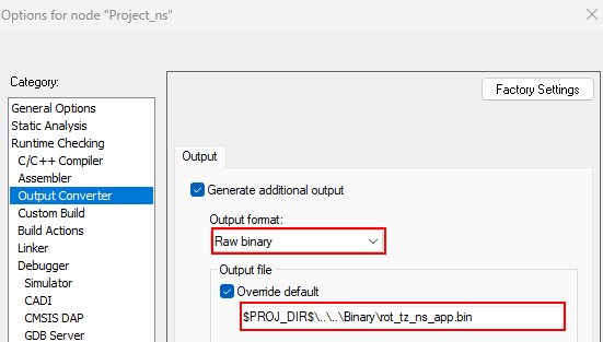
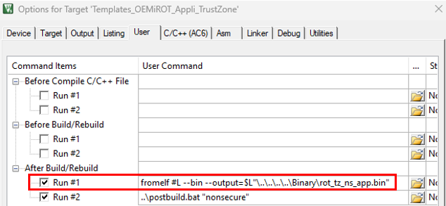
Therefore, the IDE must be configured to generate a .bin file.
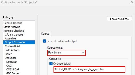
$PROJ_DIR$\..\..\Binary\rot_tz_s_app.bin$PROJ_DIR$\..\..\Binary\rot_tz_ns_app.bin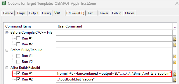
fromelf #L --bincombined --output=$L"\..\..\..\..\Binary\rot_tz_s_app.bin"fromelf #L --bin --output=$L"\..\..\..\..\Binary\rot_tz_ns_app.bin"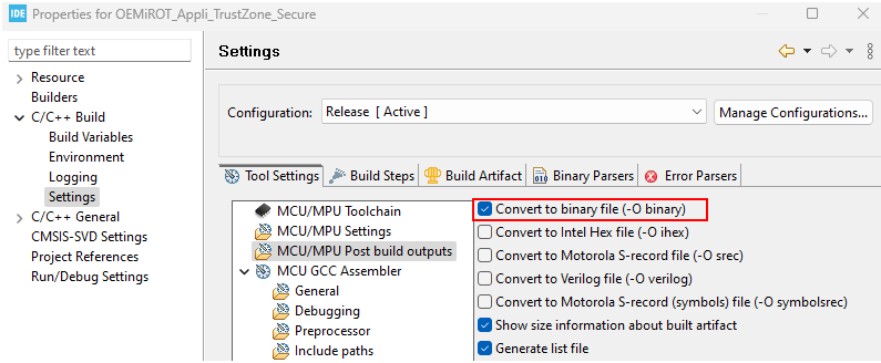
Nonsecure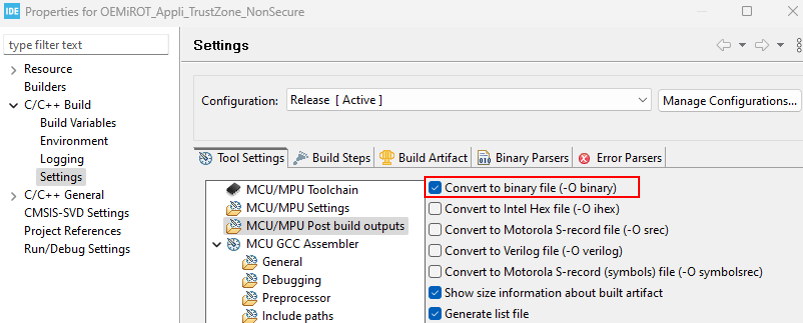
To meet the binary name and location requirements, a postbuild script is implemented to copy the binaries generated by the IDE. This script must be updated with the generated binary names to perform this operation.

The image generation can be started manually using STM32TrustedPackageCreator, but it is more efficient to modify the user application project to generate the image automatically at the end of each compilation as a postbuild command.
Refer to the figures in the STiRoT_Appli_TrustZone example to add a postbuild command.
An example of postbuild.bat/.sh is provided in the Firmware/Projects/STM32H573-DK/Templates/ROT/OEMiROT_Appli_TrustZone and Firmware/Projects/STM32H573-DK/Applications/ROT/OEMiROT_Appli_TrustZone examples. The image generation is performed based on OEMiRoT_Code_Image.xml, stored in the Firmware/Projects/STM32H573-DK/ROT_Provisioning/OEMiROT/Images folder. Depending on the location of the application, the postbuild script may be updated to access the OEMiRoT_Code_Image.xml file.
3.4. Security management
For security robustness, when OEMiRoT jumps to the user application, the MPU is configured to ensure that only the user application code area can be executed (execution surface controlled via MPU configuration). It is the responsibility of the application to reconfigure the MPU to meet the security requirements.
3.5. Ready to start
The application has now been adapted to OEMiRoT Boot path. To test it, run the provisioning.bat/sh script stored in the Firmware/Projects/STM32H573-DK/ROT_Provisioning/OEMiROT folder and follow the instructions.
For more details, refer to the following wiki pages:
- How to start with OEMiRoT on STM32H503
- How to start with OEMiRoT on STM32H533
- How to start with OEMiRoT on STM32H573 and 563 – Arm® TrustZone® enabled
4. Two boot stages: STiRoT + OEMuRoT
The adaptation of the user application for a STiRoT + OEMuRoT Boot path with two boot stages is very similar to the one-boot-stage OEMiROT use case, with two major differences:
- The location of the provisioning scripts: Firmware\Projects\STM32H573-DK\ROT_Provisioning\STiROT_OEMuROT.
- OEMuRoT is generated by compiling the OEMiRoT_Boot project with the OEMUROT_ENABLE switch activated. OEMuRoT acts as a second boot stage.


