1. Principle of SVPWM
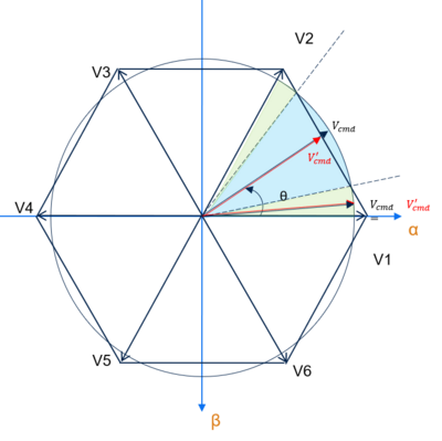
Space vector modulation index is limited to √3/2 but there is a way to extend this limit with the over-modulation. This technique is required when the modulation index, as the length of the reference space vector Us, exceeds the edges of the hexagon.
1.1. Linear mode
In the linear area, V'cmd can keep both the amplitude and angle of Vcmd ,
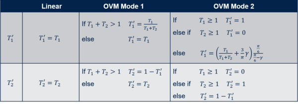
then V'cmd = T'1 * V1 + T'2 * V2 with T'1 = T1 and T'2 = T2 .
1.2. OVM mode 1
There are two cases:
- In the green area: T1 + T2 ≤ 1 .
Vcmd is unmodified and the timings remain unchanged T'1 = T1 and T'2 = T2 . In that region V'cmd follows the circle. - In the blue area: T1 + T2 > 1 .
Then In order to keep V'cmd on the edge of the hexagon and keep the angle 𝜃, | V'cmd | is shrunk to make T'1 + T'2 = 1. V'cmd = T'1 * V1 + T'2 * V2 with T'1 = T1 / (T1 + T2) and T'2 = T2 / (T1 + T2).
In that region V'cmd follows the hexagon edge.
1.3. OVM mode 2
There are three cases:
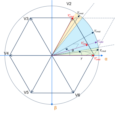
- In the green area: T1 ≥ 1.0 .
We only use V1 to generate theV'cmd .
Then V'cmd = T'1 * V1 + T'2 * V2 with T1 = 1.0 and T2 = 0 . - In the yellow area: T2 ≥ 1.0 .
We only use V2 to generate theV'cmd .
Then V'cmd = T'1 * V1 + T'2 * V2 with T1 = 0 and T2 = 1.0 . - In the blue area: T1 < 1.0 && T2 < 1.0 .
Then V'cmd = T'1 * V1 + T'2 * V2 with T'1 = (T1 / (T1 + T2) + 3 / 𝜋 . 𝛾) . (𝜋/6) / (𝜋/6 − 𝛾) and T'2 = 1.0 − T'1 .
2. Over-modulation timings sum-up
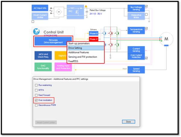
3. Over-modulation activation in STM32 MC SDK V5.Y
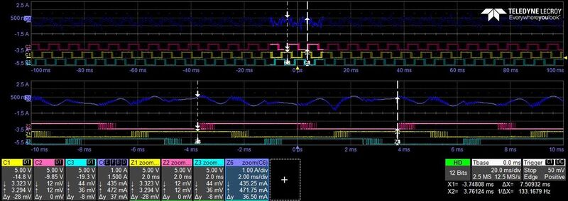
4. Over-modulation example
Example: F4 three shunt with Shinano motor at 4000 rpm
- In the middle of this snapshot: the blue curve shows the phase current
- Just bellow: the pink, yellow and green curves show the PWM channels
The over-modulation increases the total harmonic distortion, but it allows the modulation index to exceed √3/2.


