Click here for Bluetooth® LE overview
1. STM32WB dual core
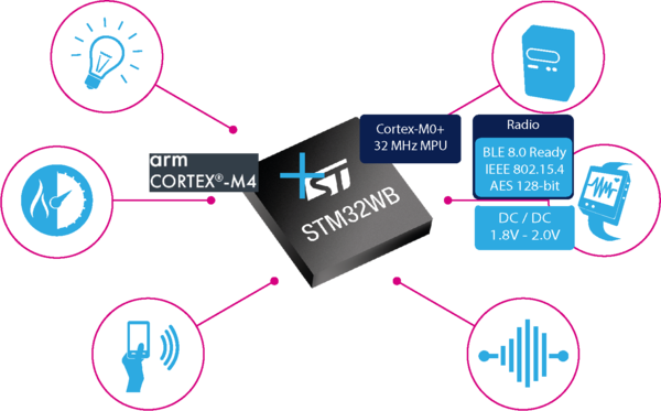
The STM32WB combines an Arm® Cortex®-M4 for the application, plus a 2.4 GHz radio subsystem and an Arm® Cortex®-M0+ processor running the firmware upgrade service (FUS) and the wireless stack .
| STM32WB dual core |
|---|
All the code running on Arm® Cortex®-M0+ (CPU2) is delivered as encrypted binary, and it is necessary to upgrade the wireless stack before developing a project on the application side.
- Black box for customer perspective
All the code running on the Arm® Cortex®-M4 (CPU1) is delivered as source code.
The STM32WB is pre-loaded with root security system (FUS) firmware necessary to authenticate the selected wireless stack (binary encrypted format) loaded by the customer on st.com.
| STM32WB memory mapping |
|---|
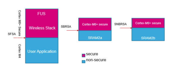
Cortex®-M0+ security protects the upper parts of the flash and SRAM2 memories. The sizes of the areas are automatically set during wireless stack install or update:
- Secure flash start address (SFSA) is the lower boundary of protected flash memory. It is aligned on 4 Kbytes(WB5x) or 2 Kbytes(WB1x) granularity.
- For STM32WB5x and STM32WB3x families:
- Secure backup RAM start address (SBRSA) and secure non-backup RAM start address (SNBRSA) are the lower address of protected parts of the SRAM2a and SRAM2b memories respectively. The size can be set with a granularity of 1 Kbytes.
- Backup SRAM2a can be used to store data when system is in standby mode.
- For STM32WB1x families:
- Secure backup RAM start address (SBRSA_A) and secure backup RAM start address (SBRSA_B) are the lower address of protected parts of the SRAM2a and SRAM2b memories respectively. The size can be set with a granularity of 1 Kbytes.
- Both can be used to store data when system is in standby mode, in addition to the SRAM1.
However, these option byte settings are the responsibility of the FUS. They are set during a first install or an update of the wireless stack. They cannot be modified by the user.
The article how to use STM32Cubeprogrammer[1] contains information to help users to upgrade the secure area of the STM32WB.
2. Hardware platform configuration
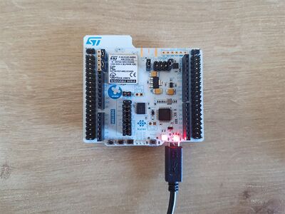
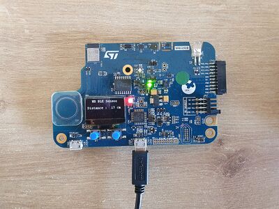
2.1. P-NUCLEO-WB55[2] and STM32WB5MM-DK Discovery kit[3]
2.1.1. Boards and ST-LINK USB cable connections
| Nucleo | Discovery Kit |
|---|---|
The USB cable from the PC is used to power and interact with the STM32:
- P-NUCLEO-WB55 : Jumper JP1 to USB STL and USB ST-LINK to be used
- STM32WB5MM-DK Discovery kit : Jumper JP2 to 1-2 and USB ST-LINK to be used
3. FUS and wireless stack update
The firmware upgrade service (FUS) and Bluetooth® Low Energy Stack can be updated using STM32CubeProgrammer software[1]
More information about the FUS can be found on the dedicated Firmware Upgrade Services wiki article or within the firmware upgrade service for STM32WB series application note[4].
3.1. How to update the FUS
The FUS (firmware upgrade services) is firmware that runs on STM32WB the Cortex®-M0+ and offers the following features:
- Install, upgrade or delete STM32WB Cortex®-M0+ wireless stack
- FUS self-upgrade
- Customer authentication key management
- User key management
- Communication with Cortex®-M4 (user code or bootloader)
The steps described below are needed in order to update the FUS of P-NUCLEO-WB55 and STM32WB5MM-DK Discovery platforms.
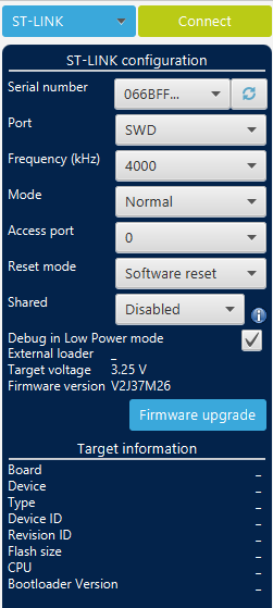
Connect your platform using STM32Cubeprogrammer[1].
| CubeProgrammer: connection |
|---|
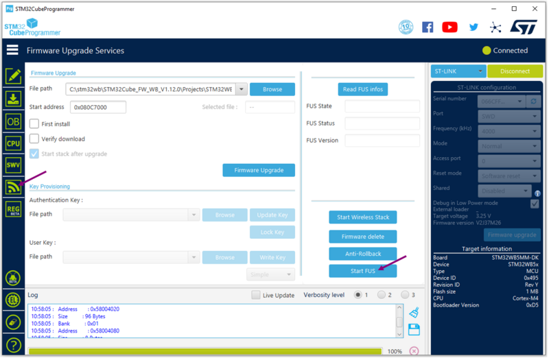
3.1.1. Start FUS
When connected, go to the firmware upgrade services interface, and start the FUS, by clicking on the associated button.
| CubeProgrammer: start FUS |
|---|
Once the FUS has started correctly, the following logs should be visible on the CubeProgrammer logs interface.
| CubeProgrammer: FUS started logs |
|---|
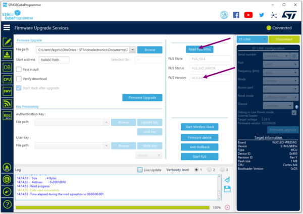
3.1.2. Read FUS
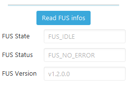
Once the FUS is started read its value by clicking the Read FUS infos button
| CubeProgrammer: read FUS |
|---|
3.1.3. Update firmware upgrade service binary
The latest version of the FUS can be found in STM32CubeWB MCU Package[5].
Check the release notes to find the latest FUS version and the FUS start address.
| FUS information |
|---|
If the FUS version of your platform is different to the version specified in the release notes, proceed to the FUS update by following the steps below:
- If the platform FUS version is 0.5.3, use the dedicated binary:
STM32Cube_FW_WB_V[...]\Projects\STM32WB_Copro_Wireless_Binaries\STM32WB5x\stm32wb5x_FUS_fw_for_fus_0_5_3.bin
.
| CubeProgrammer: FUS 0.5.3 |
|---|
- If the platform FUS version is different to 0.5.3, then use the other binary:
STM32Cube_FW_WB_V[...]\Projects\STM32WB_Copro_Wireless_Binaries\STM32WB5x\stm32wb5x_FUS_fw.bin
.
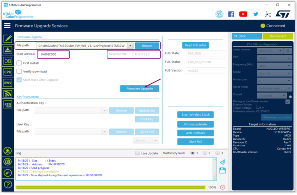
Complete the file path with the correct file and add start address (see release notes).
Click on Firmware Upgrade.
| CubeProgrammer: update FUS |
|---|
A popup occurs to confirm that the upgrade is correct.
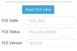
3.1.4. Check new FUS version
Check the new FUS version by clicking on the Read FUS info button.
| CubeProgrammer: read new FUS |
|---|
3.2. How to update the Bluetooth® LE Wireless Stack
The Bluetooth® LE Stack can be updated in the same way as the FUS.
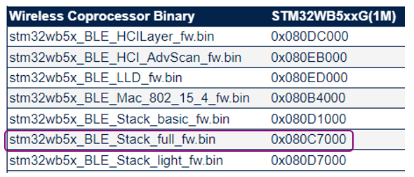
First, check the start address of the stack in the release notes.
| Stack start address |
|---|
Select the type of stack to be loaded in the STM32CubeWB package[5].
For P-NUCLEO-WB55 and STM32WB5MM-DK Discovery platforms; the Bluetooth® LE stack recommended is:
STM32Cube_FW_WB_V[...]\Projects\STM32WB_Copro_Wireless_Binaries\STM32WB5x\stm32wb5x_BLE_Stack_full_fw.bin.
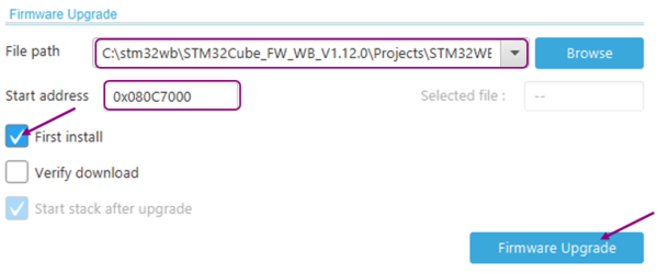
Check the First install checkbox if it is the first time you are installing the stack on your platform.
| CubeProgrammer: stack installation |
|---|
3.3. How to check that the Bluetooth® LE Application is up and running
To ensure FUS and Bluetooth® LE stack are fully functional, it is necessary to load an application on the Arm® Cortex®-M4. The STM32CubeWB package[5] provides different applications
.
Example project binaries are provided in STM32CubeWB package[5]
- for P-NUCLEO-WB55 board:
- STM32Cube_FW_WB_V[...]\Projects\P-NUCLEO-WB55.Nucleo\Applications\BLE\[...].
- STM32Cube_FW_WB_V[...]\Projects\P-NUCLEO-WB55.Nucleo\Applications\BLE\[...].
- for STM32WB5MM-DK board:
- STM32Cube_FW_WB_V[...]\Projects\STM32WB5MM-DK\Applications\BLE\[...].
- STM32Cube_FW_WB_V[...]\Projects\STM32WB5MM-DK\Applications\BLE\[...].
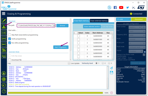
The following steps show to install and launch the BLE_p2pServer project on the board.
- Go to the Erasing and programming interface.
- Select the path to the application binary, for example: STM32Cube_FW_WB_V[...]\Projects\[...]\Applications\BLE\BLE_p2pServer\Binary\BLE_p2pServer_reference.hex.
- Click on the Start Programming button.
| CubeProgrammer: install application |
|---|
Once the application is correctly loaded into the platform flash memory, open a terminal as described in with the Debug Interface Chapter and reset the platform.
Once the board is connected and the terminal window set up, press the reset button of the board. The following messages are printed to the virtual COM window when the firmware starts successfully: At this point the FUS and Bluetooth® LE Stack are correctly installed on your platforms, BLE_p2pServer application prints the following messages to the virtual COM window when the firmware starts successfully:
- FUS and Bluetooth® LE stack version are displayed on terminal log:
| application startup logs |
|---|
- More information how to Build & Install Bluetooth® LE Application .
- To play with the BLE_p2pServer application more information is available in UM2551 - STM32CubeWB Nucleo demonstration firmware
3.4. Debug log via UART interface
The P-NUCLEO-WB55 and STM32WB5MM-DK platforms embed the ST-LINK/V2 in-circuit debugger and programmer for STM32 microcontrollers. The single-wire interface module (SWIM) and JTAG/serial wire debugging (SWD) interfaces are used to communicate with the STM32WB microcontroller. It also supports the STM32 virtual COM port driver for communication between a PC and the application processor via a serial interface.
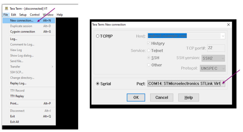
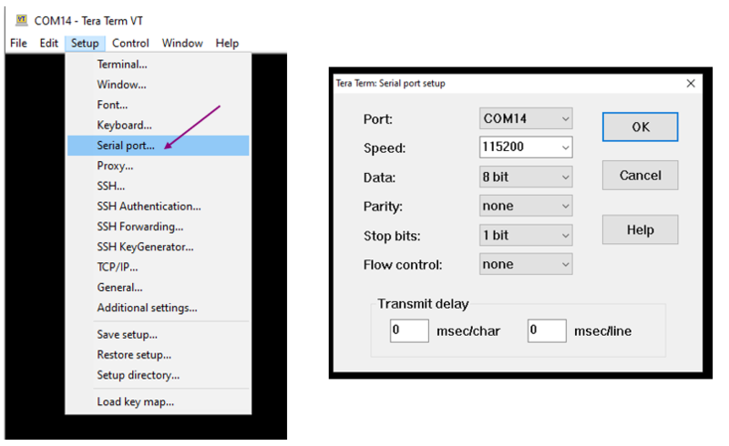
Use any convenient software terminal to open the serial communication port of the PC to check the messages from the board. Select your serial port and set up your connection as follows (example done with Tera Term software).
Set a new serial connection to the ST platform:
| Tera Term setup (1/2) |
|---|
Setup your serial connection as below:
| Tera Term setup (2/2) |
|---|
4. Related video
Further information can be found on the following videos:
Getting Started: Stack loading
Getting Started: STM32WB USB Dongle
Stack and FUS Update over USB bootloader
5. Going further
- Create your own Bluetooth® LE example Using CubeMX : STM32CubeMX article
- Build and load the flash memory of an existing example : Build Bluetooth® LE Project article
6. References
