Click here for Cellular overview
1. Introduction
This wiki article provides information to help end users with their hardware setup.
X-CUBE-CELLULAR supports different types of hardware setup.
Some setups are based on a module that contains both an STM32 and a modem while some others are based on two boards, an STM32 board associated with a separate modem board.
If the STM32 board has no STMod+ connector, use an ARDUINO® / STMod+ adaptor, this is the case for the B-L4S5I-IOT01A[1].
Separate STM32 and modem boards are sometimes available as one pack composed of two boards in the same blister, this is the case for the P-L496G-CELL02[2].
In case of any issue, do not forget to check the ST-LINK firmware version and upgrade it if necessary. For this purpose use the STM32CubeProgrammer tool (STM32CubeProg[3]) .
Depending on the end user PC's OS a USB driver might be required.
Note that when GM01Q-STMOD[4] is mentioned it can be replaced by GMS01Q-STMOD[5]
GMS01Q is a GM01Q with an Orange provisioned embedded SIM.
Note that the hardware setups listed are not all available depending on the software version. For complete information see the Release Note associated with the software delivery.
2. Modem FW version
The modem factory FW version in the user HW may not be compliant any longer with the latest X-CUBE-CELLULAR version. The Cellular modem RN indicates which modem FW version must be used. The modem FW version must be checked in the serial terminal trace and updated if necessary.
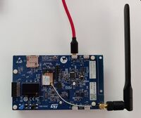
3. B-L462E-CELL1[6]
3.1. Boards and ST-LINK USB cable connections
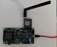
The red USB cable (not provided) from the PC is used to power and interact with the STM32.
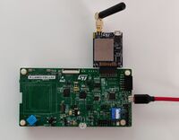
4. P-L496G-CELL02 [2]
4.1. Boards and ST-LINK USB cable connections
The red USB cable (not provided) from the PC is used to power and interact with the STM32.
5. B-U585I-IOT02A[7] + GM01Q-STMOD[4] or STEVAL-STMODLTE[8]
5.1. Boards and ST-LINK USB cable connections
The red USB cable (not provided) from the PC is used to power and interact with the STM32.
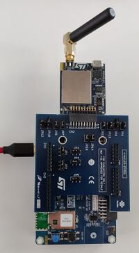
6. B-L4S5I-IOT01A[1] + X-NUCLEO-STMODA1[9] + GM01Q-STMOD[4] or STEVAL-STMODLTE[8]
6.1. Boards and ST-LINK USB cable connections
The red USB cable (not provided) from the PC is used to power and interact with the STM32.
7. 32L496GDISCOVERY[10] + GM01Q-STMOD[4] or STEVAL-STMODLTE[8]
7.1. Boards and ST-LINK USB cable connections
The red USB cable (not provided) from the PC is used to power and interact with the STM32.
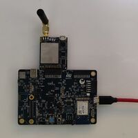
8. STEVAL-STWINKT1B[11] + GM01Q-STMOD[4] or STEVAL-STMODLTE[8]
8.1. Boards and ST-LINK USB cable connections
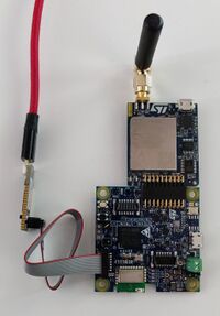
The red USB cable (not provided) from the PC is used to interact with the STM32 through the STLINK-V3. This STLINK-V3 is provided in the blister.
A second USB cable (not provided, not shown in the figure above) is required to power the STEVAL-STWINKT1B[11] through its USB connector.
9. Previous X-CUBE-CELLULAR versions, hardware no more supported
The former X-CUBE-CELLULAR versions support other hardware setups such as P-L496G-CELL01[12] (similar to P-L496G-CELL02[2] but with the UG96 Quectel 2G/3G modem), and B-L475E-IOT01A[13].
UG96 is no more used because, nowadays, LTE Cat M and NB-IoT networks are available and much more low-power friendly than 3G.
B-L475E-IOT01A[13] (also known as "IoT node V1") is replaced with B-L4S5I-IOT01A[1] (also known as "IoT node V1.5").
XCC V7.0.0 onwards the STWINKT1B is no more supported.
10. References
- ↑ 1.0 1.1 1.2 B-L4S5I-IOT01A
- ↑ 2.0 2.1 2.2 P-L496G-CELL02
- ↑ STM32CubeProg
- ↑ 4.0 4.1 4.2 4.3 4.4 GM01Q-STMOD
- ↑ GMS01Q-STMOD
- ↑ B-L462E-CELL1
- ↑ B-U585I-IOT02A
- ↑ 8.0 8.1 8.2 8.3 STEVAL-STMODLTE
- ↑ X-NUCLEO-STMODA1
- ↑ 32L496GDISCOVERY
- ↑ 11.0 11.1 STEVAL-STWINKT1B
- ↑ P-L496G-CELL01
- ↑ 13.0 13.1 B-L475E-IOT01A
