Sensing is a major part of smart objects and equipment, for example, condition monitoring for predictive maintenance, which enables context awareness and production performance improvement, and results in a drastic decrease in downtime due to preventive maintenance.
The FP-AI-MONITOR2 function pack is a multisensor AI data monitoring framework on the wireless industrial node, for STM32Cube. It helps to jump-start the implementation and development of sensor-monitoring-based applications designed with the X-CUBE-AI, an Expansion Package for the STM32Cube, or with the NanoEdge™ AI Studio, an autoML tool for generating AI models for tiny microcontrollers. It covers the entire design of the machine learning cycle, from the data set acquisition to the integration and deployment on a physical node.
The FP-AI-MONITOR2 runs learning and inference sessions in real-time on the SensorTile wireless industrial node development kit box (STEVAL-STWINBX1), taking data from onboard sensors as input. The FP-AI-MONITOR2 implements a wired interactive CLI to configure the node and manage the learn and detect phases. For simple in-the-field operation, a standalone battery-operated mode is also supported, which allows basic controls through the user button, without using the console.
The STEVAL-STWINBX1 has an STM32U585AIIxQ microcontroller, which is an ultra-low-power Arm® Cortex®-M33 MCU, with FPU and TrustZone® at 160 MHz, 2 Mbytes of flash memory, and 786 Kbytes of SRAM. In addition, the STEVAL-STWINBX1 embeds industrial-grade sensors, including a 6-axis IMU, 3-axis accelerometer and vibrometer, and analog microphones to record any inertial, vibrational, and acoustic data on the field with high accuracy at high sampling frequencies.
The rest of the article discusses the following topics:
- The required hardware and software,
- Prerequisites and setup,
- FP-AI-MONITOR2 console application,
- Running a human activity recognition (HAR) application for sensing on the device,
- Running an anomaly detection application using NanoEdge™ AI libraries on the device,
- Running an n-class classification application using NanoEdge™ AI libraries on the device,
- Running an advance dual model on the device, which combines anomaly detection using NanoEdge™ AI libraries based on vibration data and CNN-based n-class classification based on ultrasound data,
- Performing the vibration and ultrasound sensor data collection using a prebuilt binary of FP-SNS-DATALOG2,
- Button-operated modes, and
- Some links to useful online resources, to help the user better understand and customize the project for her/his own needs.
This article is just to serve as a quick starting guide and for full FP-AI-MONITOR2 user instructions, readers are invited to refer to the FP-AI-MONITOR2 user manual.
1. Hardware and software overview
1.1. STWIN.box - SensorTile wireless industrial node development kit
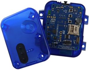
The STWIN.box (STEVAL-STWINBX1) is a development kit and reference design that simplifies the prototyping and testing of advanced industrial sensing applications in IoT contexts such as condition monitoring and predictive maintenance.
It is powered with Ultra-low-power Arm® Cortex®-M33 MCU with FPU and TrustZone® at 160 MHz, with 2048 kBytes of flash memory (STM32U585AI).
It is an evolution of the original STWIN kit (STEVAL-STWINKT1B) and features a higher mechanical accuracy in the measurement of vibrations, improved robustness, an updated BOM to reflect the latest and best-in-class MCU and industrial sensors, and an easy-to-use interface for external add-ons.
The STWIN.box kit consists of an STWIN.box core system, a 480mAh LiPo battery, an adapter for the ST-LINK debugger, a plastic case, an adapter board for DIL 24 sensors, and a flexible cable.
Other features:
- A microSD™ card slot for standalone data logging applications
- On-board Bluetooth® Low Energy v5.0 wireless technology (BlueNRG-M2), Wi-Fi (EMW3080), and NFC (ST25DV04K)
- Option to implement authentication and brand protection secure solution with STSAFE-A110
- Wide range of industrial IoT sensors:
- Ultra-wide bandwidth (up to 6 kHz), low-noise, 3-axis digital vibration sensor (IIS3DWB)
- 3D accelerometer and 3D gyroscope iNEMO inertial measurement unit (ISM330DHCX) with machine learning core
- High-performance ultra-low-power 3-axis accelerometer for industrial applications (IIS2DLPC)
- Ultra-low-power 3-axis magnetometer (IIS2MDC)
- High-accuracy, high-resolution, low-power, 2-axis digital inclinometer with embedded machine learning core (IIS2ICLX)
- Dual full-scale, 1.26 bar and 4 bar, absolute digital output barometer in full-mold package (ILPS22QS)
- Low-voltage, ultra-low-power, 0.5°C accuracy I²C/SMBus 3.0 temperature sensor (STTS22H)
- Industrial grade digital MEMS microphone (IMP34DT05)
- Analog MEMS microphone with a frequency response of up to 80 kHz (IMP23ABSU)
- Expandable via a 34-pin FPC connector
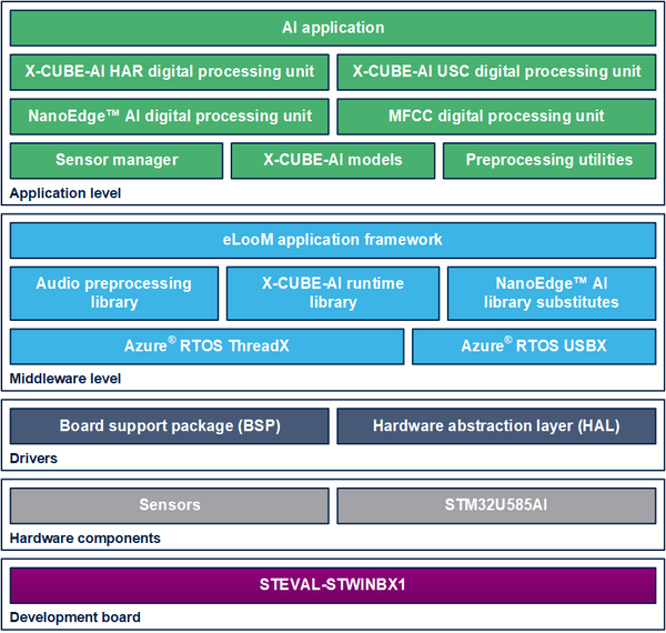
1.2. Software architecture
The top-level architecture of the FP-AI-MONITOR2 function pack is shown in the following figure.
2. Prerequisites and setup
2.1. Hardware prerequisites and setup
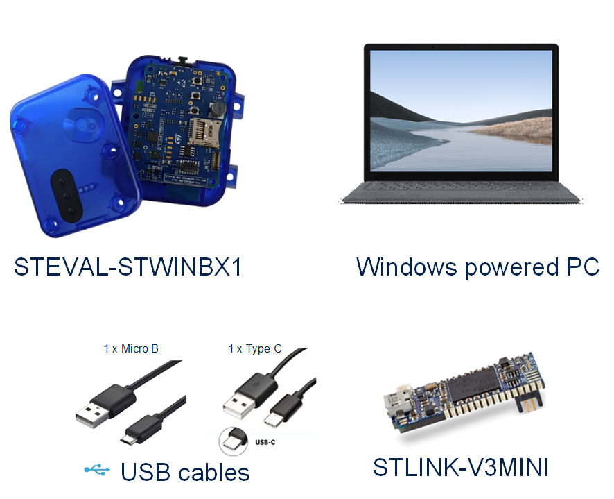
To use the FP-AI-MONITOR2 function pack on STEVAL-STWINBX1, the following hardware items are required:
- STEVAL-STWINBX1 development kit board,
- A microSD™ card and card reader to log and read the sensor data,
- Windows® powered laptop/PC,
- A USB Type-C® cable, to connect the sensor board to the PC
- A USB Micro-B cable, for the STLINK-V3MINI, and
- A STLINK-V3MINI.
2.2. Software requirements
2.2.1. FP-AI-MONITOR2
- Download the latest version of the FP-AI-MONITOR2 package from the ST website, and extract and copy the .zip file contents into a folder on the PC. The package contains binaries, source code, and utilities for the sensor board STEVAL-STWINBX1.
2.2.2. STM32CubeProgrammer
- STM32CubeProgrammer is an all-in-one multi-OS software tool for programming STM32 products. It provides an easy-to-use and efficient environment for reading, writing, and verifying device memory through both the debug interface (JTAG and SWD) and the bootloader interface (UART, USB DFU, I²C, SPI, and CAN). STM32CubeProgrammer offers a wide range of features to program STM32 internal memories (such as flash, RAM, and OTP) as well as external memory. Download the latest version of the STM32CubeProgrammer. The FP-AI-MONITOR2 is tested with the STM32CubeProgrammer version 2.12.0.
- This software is available from STM32CubeProg.
2.2.3. Tera Term
- Tera Term is an open-source and freely available software terminal emulator, which is used to host the CLI of the FP-AI-MONITOR2 through a serial connection.
- Users can download and install the latest version available from the Tera Term website.
2.3. Installing the function pack
2.3.1. Getting the function pack
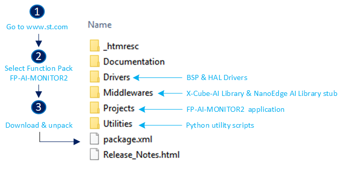
The first step is to get the function pack FP-AI-MONITOR2 from the ST website. Once the pack is downloaded, unpack/unzip it and copy the content to a folder on the PC. The steps of the process along with the content of the folder are shown in the following image.
2.3.2. Flashing the application on the sensor board
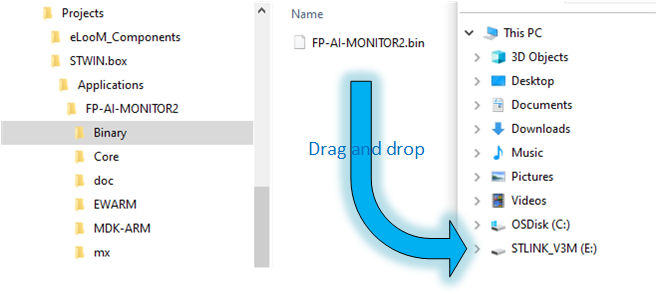
This section explains how to select a binary file for the firmware and program it into the STM32 microcontroller. A precompiled binary file is delivered as part of the FP-AI-MONITOR2 function pack. It is located in the FP-AI-MONITOR2_V1.0.0\Projects\STWIN.box\Applications\FP-AI-MONITOR2\Binary\ folder. When the STM32 board and PC are connected through the USB cable on the STLINK-V3E connector, the STEVAL-STWINBX1 appears as a drive on the PC. The selected binary file for the firmware can be installed on the STM32 board by simply performing a drag-and-drop operation as shown in the figure below. This creates a dialog to copy the file and once it disappears (without any error) this indicates that the firmware is programmed in the STM32 microcontroller.
3. FP-AI-MONITOR2 console application
FP-AI-MONITOR2 provides an interactive command-line interface (CLI) application. This CLI application equips a user with the ability to configure and control the sensor node, and to perform different AI operations on the edge, including learning and anomaly detection (for NanoEdge™ AI libraries), n-Class classification (NanoEdge™ AI libraries), dual (combination of NanoEdge™ AI detection and CNN based classification), and human activity recognition using CNN and scikit-learn models. The following sections provide a small guide on how to install this CLI application on a sensor board and control it through the serial connection from TeraTerm.
3.1. Setting up the console
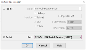
Once the sensor board is programmed with the binary of the project, the next step is to set up the serial connection of the board with the PC through TeraTerm. To do so, start TeraTerm, and select the proper connection, featuring the [USB serial device]. For the screenshot below this is COM5, but it might vary for every user.
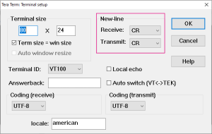
Set the terminal parameters:
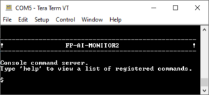
Restart the board by pressing the RESET button. The following welcome screen is displayed on the terminal.
From this point, start entering the commands directly or type help to get the list of available commands along with their usage guidelines.
3.2. Configuring the sensors
Through the CLI interface, a user can configure the supported sensors for sensing and condition monitoring applications. The list of all the supported sensors can be displayed on the CLI console by entering the command sensor_info. This command prints the list of the supported sensors along with their ids as shown in the snippet below. The user can configure these sensors using these ids. The configurable options for these sensors include:
- enable: to activate or deactivate the sensor,
- ODR: to set the output data rate of the sensor from the list of available options, and
- FS: to set the full-scale range from the list of available options.
The current value of any of the parameters for a given sensor can be printed using the command,
$ sensor_get <sensor_id> <param>
or all the information about the sensor can be printed using the command:
$ sensor_get <sensor_id> all
Similarly, the values for any of the available configurable parameters can be set through the command:
$ sensor_set <sensor_id> <param> <val>
The snippet below shows the complete example of getting and setting these values along with old and changed values.
$ sensor_info
imp34dt05  ID=0 , type=MIC
iis3dwb    ID=1 , type=ACC
ism330dhcx ID=2 , type=ACC
ism330dhcx ID=3 , type=GYRO
imp23absu  ID=5 , type=MIC
iis2iclx   ID=6 , type=ACC
stts22h    ID=7 , type=TEMP
ilps22qs   ID=8 , type=PRESS
iis2dlpc   ID=9 , type=ACC
iis2mdc    ID=10, type=MAG
-------
10 sensors supported

$ sensor_get 1 all
enable = false
nominal ODR = 26667.00 Hz, latest measured ODR = 0.00 Hz
Available ODRs:
26667.00 Hz
fullScale = 16.00 g
Available fullScales:
2.00 g
4.00 g
8.00 g
16.00 g

$ sensor_set 1 enable 1
sensor 1: enable

$ sensor_set 1 FS 4
sensor FS: 4.00

$ sensor_get 1 all
enable = true
nominal ODR = 26667.00 Hz, latest measured ODR = 0.00 Hz
Available ODRs:
26667.00 Hz
fullScale = 4.00 g
Available fullScales:
2.00 g
4.00 g
8.00 g
16.00 g
4. Inertial data classification with STM32Cube.AI
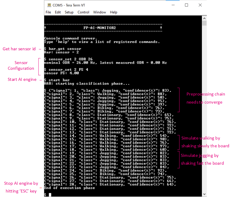
The CLI application comes with a prebuilt Human Activity Recognition model. This functionality is started by typing the command:
$ start har
Note that the provided HAR model is built with a dataset created using the ISM330DHCX_ACC sensor with ODR = 26, and FS = 4. To achieve the best performance, the user must set these parameters to the sensor configuration using the sensor_set command as provided in the Command Summary table.
Running the $ start har command starts doing the inference on the accelerometer data and predicts the performed activity along with the confidence. The supported activities are:
- Stationary,
- Walking,
- Jogging, and
- Biking.
The following figure is a screenshot of the normal working session of the har command in the CLI application.
5. Anomaly detection with NanoEdge™ AI library
FP-AI-MONITOR2 includes a pre-integrated stub that is easily replaced by an AI condition monitoring library generated and provided by NanoEdge™ AI Studio. This stub simulates the NanoEdge™ AI-related functionalities, such as running learning and detection phases on the edge.
The learning phase is started by issuing a command $ start neai_learn from the CLI console or by long-pressing the [USR] button. The learning process is reported either by slowly blinking the green LED light on STEVAL-STWINBX1 or in the CLI as shown below:
$ NanoEdge AI: learn
CTRL:! This is a stubbed version, install the NanoEdge AI library!
{"signal": 1, "status": "need more signals"},
{"signal": 2, "status": "need more signals"},
:
:
{"signal": 10, "status": success}
{"signal": 11, "status": success}
:
:
End of the execution phase
The CLI shows that the learning is being performed at every signal learned. The NanoEdge AI library requires learning for at least ten samples, so for all the samples until the ninth sample a status message saying 'need more signals' is printed along with the signal id. Once 10 signals are learned, the status of 'success' is printed. The learning can be stopped by pressing the ESC key on the keyboard or simply by pressing the [USR] button.
Similarly, the user starts the condition monitoring process by issuing the command $ start neai_detect. This starts the inference phase. The anomaly detection phase checks the similarity of the presented signal with the learned normal signals. If the similarity is less than the set threshold default of 90%, a message is printed in the CLI showing the occurrence of an anomaly along with the similarity of the anomaly signal.
The process is stopped by pressing the ESC key on the keyboard or pressing the [USR] button.
This behavior is shown in the snippet below:
$ start neai_detect
NanoEdgeAI: starting detect phase...

$ NanoEdge AI: detect
CTRL:! This is a stubbed version, install the NanoEdge AI library!
{"signal": 1, "similarity": 0, "status": anomaly},
{"signal": 2, "similarity": 1, "status": anomaly},
{"signal": 3, "similarity": 2, "status": anomaly},
:
:
{"signal": 90, "similarity": 89, "status": anomaly},
{"signal": 91, "similarity": 90, "status": anomaly},
{"signal": 102, "similarity": 0, "status": anomaly},
{"signal": 103, "similarity": 1, "status": anomaly},
{"signal": 104, "similarity": 2, "status": anomaly},
End of the execution phase
Other than CLI, the status is also presented using the LED lights on the STEVAL-STWINBX1. Fast blinking green LED light shows that the detection is in progress. Whenever an anomaly is detected, the orange LED light blinks twice to report an anomaly. If not enough signals (at least 10) are learned, a message saying "need more signals" with a similarity value equal to 0 appears.
NOTE: This behavior is simulated using a STUB library where the similarity starts from 0 when the detection phase is started and increments with the signal count. Once the similarity reaches 100, it resets to 0. One can see that the anomalies are not reported when the similarity is between 90 and 100.
5.1. Additional parameters in condition monitoring
For user convenience, the CLI application also provides handy options to easily fine-tune the inference and learning processes. The list of all the configurable variables is available by issuing the following command:
$ neai_get all
signals     = 0
sensitivity = 1.00
threshold   = 90
timer       = 0 ms
sensor      = 7
Each of these parameters is configurable using the neai_set <param> <val> command.
This section provides information on how to use these parameters to control the learning and detection phase. By setting the "signals" and "timer" parameters, the user can control how many signals or for how long the learning and detection are performed (if both parameters are set the learning or detection phase stops whenever the first condition is met). For example, to learn 10 signals, the user issues this command, before starting the learning phase as shown below.
$ neai_set signals 10
signals set to 10

$ start neai_learn
NanoEdgeAI: starting learn phase...

$ NanoEdge AI: learn
CTRL:! This is a stubbed version, install the NanoEdge AI library!
{"signal": 1, "status": "need more signals"},
{"signal": 2, "status": "need more signals"},
...
{"signal": 9, "status": "need more signals"},
{"signal": 10, "status": "success"},
End of the execution phase
If both of these parameters are set to "0" (default value), the learning and detection phases run indefinitely.
The threshold parameter is used to report any anomalies. For any signal that has similarities below the threshold value, an anomaly is reported. The default threshold value used in the CLI application is 90. Users can change this value by using the neai_set threshold <val> command.
Finally, the sensitivity parameter is used as an emphasis parameter. The default value is set to 1. Increasing this sensitivity means that the signal matching is to be performed more strictly, reducing it relaxes the similarity calculation process, meaning resulting in higher matching values.
For further details on how NanoEdge™ AI libraries work users are invited to read the detailed documentation of NanoEdge™ AI Studio.
6. n-class classification with NanoEdge™ AI
This section provides an overview of the classification application provided in FP-AI-MONITOR2 based on the NanoEdge™ AI classification library. FP-AI-MONITOR2 includes a pre-integrated stub, which is easily replaced by an AI classification library generated using NanoEdge™ AI Studio. This stub simulates the NanoEdge™ AI-classification-related functionality, such as running the classification by simply iterating between two classes for ten consecutive signals on the edge.
Unlike the anomaly detection library, the classification library from the NanoEdge™ AI Studio comes with static knowledge of the data and does not require any learning on the device. This library contains the functions based on the provided sample data to classify the best class from another and rightfully assign a label to it when performing the detection on the edge. The classification application powered by NanoEdge™ AI can be simply started by issuing a command $ start neai_class as shown in the snippet below.
$ start neai_class
NanoEdgeAI: starting classification phase...

$ CTRL:! This is a stubbed version, install the NanoEdge AI library!
NanoEdge AI: classification
{"signal": 1, "class": Class1}
{"signal": 2, "class": Class1}
:
:
{"signal": 10, "class": Class1}
{"signal": 11, "class": Class2}
{"signal": 12, "class": Class2}
:
:
{"signal": 20, "class": Class2}
{"signal": 21, "class": Class1}
:
:
End of the execution phase
The CLI shows that for the first ten samples, the class is detected as "Class1" while for the upcoming ten samples "Class2" is detected as the current class. The classification phase can be stopped by pressing the ESC key on the keyboard or simply by pressing the [USR] button.
NOTE: This behavior is simulated using a STUB library where the classes are iterated by displaying ten consecutive labels for one class and then ten labels for the next class and so on.
7. Dual-mode application with STM32Cube.AI and NanoEdge™ AI
In addition to the two applications described in the sections above, the FP-AI-MONITOR2 also provides an advanced execution phase called the dual application mode. This mode uses anomaly detection based on the NanoEdge™ AI library and performs classification using a prebuilt ANN model based on an analog microphone. The dual mode works in a power-saver configuration. A low-power anomaly detection algorithm based on the NanoEdge™ AI library is always running based on vibration data and an ANN classification based on a high-frequency analog microphone pipeline is only triggered if an anomaly is detected. Other than this both applications are independent of each other. This is also worth mentioning that the dual mode is created to work for a USB fan when the fan is running at the maximum speed and does not work very well when tested at other speeds. The working of the applications is very simple.
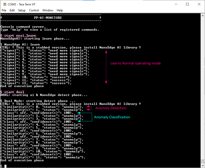
To start testing the dual application execution phase, the user first needs to train the anomaly detection library using the $ start neai_learn at the highest speeds of the fan. Once the normal conditions are learned, the user can start the dual application by issuing a simple command as $ start dual as shown in the below snippet:
Whenever there is an anomaly detected, meaning a signal with a similarity of less than 90%, the ultrasound-based classifier is started. Both applications run in asynchronous mode. The ultrasound-based classification model takes almost one second of data, then preprocesses it using the mel-frequency cepstral coefficients (MFCC), and then feeds it to a pre-trained neural network. It then prints the label of the class along with the confidence. The network is trained for four classes ['Off', 'Normal', 'Clogging', 'Friction'] to detect fan in 'Off' condition, or running in 'Normal' condition at max speed or clogged and running in 'Clogging' condition at maximum speed or finally if there is friction being applied on the rotating axis it is labeled as 'Friction' class. As soon as the anomaly detection detects the class to be normal, the ultrasound-based ANN is suspended.
8. Button-operated modes
This section provides details of the button-operated mode for FP-AI-MONITOR2. The purpose of this mode is to enable the users to operate the FP-AI-MONITOR2 on STWIN.box even in the absence of the CLI console.
In button-operated mode, the sensor node can be controlled through the user button instead of the interactive CLI console. The default values for node parameters and settings for the operations during auto-mode are provided in the firmware. Based on these configurations, different modes such as dual_mode, neai_learn, and "neai_detect" can be started and stopped through the user button on the node.
8.1. Interaction with user
The button-operated mode can work with or without the CLI and is fully compatible and consistent with the current definition of the serial console and its command-line interface (CLI).
The supporting hardware for this version of the function-pack (STEVAL-STWINBX1) is fitted with three buttons:
- User Button, the only button usable by the SW,
- Reset Button, connected to STM32 MCU reset pin,
- Power Button connected to power management,
and three LEDs:
- LED_1 (green), controlled by Software,
- LED_2 (orange), controlled by Software,
- LED_C (red), controlled by Hardware, indicates charging status when powered through a USB cable.
So, the basic user interaction for button-operated operations is to be done through two buttons (user and reset) and two LEDs (green and orange). The following provides details on how these resources are allocated to show the users what execution phases are active or to report the status of the sensor node.
8.1.1. Button Allocation
Power button allows to control powering of the device when connected to its loaded battery:
| Button Press | Description | Action |
|---|---|---|
| LONG_PRESS | The button is pressed for more than (200 ms) and released | powers up the device |
| SHORT_PRESS | The button is pressed for less than (200 ms) and released | powers down the device |
In the extended autonomous mode, the user can trigger any of the three execution phases. The available modes are:
- idle: the system is waiting for a command.
- dual: runs the X-CUBE-AI library and prints the results of the live inference on the CLI (if CLI is available) and the NanoEdge™ AI library to detect anomalies.
- neai_learn: All data coming from the sensor is passed to the NanoEdge™ AI library to train the model.
To trigger these phases, the FP-AI-MONITOR2 is equipped with the support of the user button. In the STEVAL-STWINBX1 sensor node, there are two software usable buttons:
- The user button: This button is fully programmable and is under the control of the application developer.
- The reset button: This button is used to reset the sensor node and is connected to the hardware reset pin, thus is used to control the software reset. It resets the knowledge of the NanoEdge™ AI libraries, the context variables, and sensor configurations to the default values.
To control the execution phases, we need to define and detect at least three different button press modes of the user button.
The followings are the pressing types available for the user button and their assignments to perform different operations:
| Button Press | Description | Action |
|---|---|---|
| SHORT_PRESS | The button is pressed for less than (200 ms) and released | Starts the dual mode that combines anomaly detection and anomaly classification. |
| LONG_PRESS | The button is pressed for more than (200 ms) and released | Starts the anomaly detection learning phase. |
| ANY_PRESS | The button is pressed and released (overlaps with the three other modes) | Stops the current running execution phase. |
8.1.2. LED Allocation
In the function pack six execution phases exist:
- idle: The system waits for user input.
- har: All data coming from the sensors are passed to the X-CUBE-AI library to perform HAR.
- neai learn: All data coming from the sensors are passed to the NanoEdge™ AI library to train the model.
- neai detect: All data coming from the sensors are passed to the NanoEdge™ AI library to detect anomalies.
- neai class: All data coming from the sensors are passed to the NanoEdge™ AI library to perform classification.
- dual mode: All data coming from the sensors are passed to the NanoEdge™ AI library to detect anomalies and to the X-CUBE-AI library to classify them.
At any given time, the user needs to be aware of the current active execution phase. We also need to report on the outcome of the detection when the detect execution phase is active, telling the user if an anomaly has been detected, or what activity is being performed by the user with the HAR application when the "ai detect" context is running.
The onboard LEDs indicate the status of the current execution phase by showing which context is running and also by showing the output of the context (anomaly or one of the four activities in the HAR case).
The green LED is used to show the user which execution context is being run.
| Pattern | Task |
|---|---|
| OFF | - |
| ON | IDLE |
| BLINK_SHORT | X-CUBE-AI Running |
| BLINK_NORMAL | NanoEdge™ AI learn |
| BLINK_LONG | NanoEdge™ AI detection or classification or dual-mode |
The Orange LED is used to indicate the output of the running context as shown in the table below:
| Pattern | Reporting |
|---|---|
| OFF | Stationary (HAR) when in X-CUBE-AI mode, Normal Behavior when in NEAI mode |
| ON | Biking (HAR) |
| BLINK_SHORT | Jogging (HAR) |
| BLINK_LONG | Walking (HAR) or anomaly detected (NanoEdge™ AI detection or dual-mode) |
Looking at these LED patterns the user is aware of the state of the sensor node even when CLI is not connected.
- FP-AI-MONITOR2: Multisensor AI data monitoring framework on a wireless industrial node, function pack for STM32Cube
- Getting started guide: QSG for FP-AI-MONITOR2
- How to perform anomaly detection using FP-AI-MONITOR1: A step-by-step guide to implementing an anomaly detection solution for a USB-powered fan.
- STEVAL-STWINBX1: STWIN.box - SensorTile wireless industrial node development kit
- STM32CubeMX: STM32Cube initialization code generator
- X-CUBE-AI: expansion pack for STM32CubeMX
- NanoEdge™ AI Studio: NanoEdge™ AI first machine learning software, specifically developed to entirely run on microcontrollers.
- DB4598: Data brief for STEVAL-STWINBX1.
- UM2965: Getting started with the STEVAL-STWINBX1 SensorTile wireless industrial node development kit.
