1. Introduction
Understanding and diagnosing power supply issues is essential in the electronics field, as the power supply is an important component that ensures the integrity of an application. This Wiki article presents an examination of power supply failure symptoms and their possible causes, with the goal of enabling readers to identify sources and risks of failure. The content is based on observations within actual applications, aiming to validate the coherence of components and the reliability of the power supply in a real-world setting.
For a solid foundation in the subject matter, familiarity with the Basics of power supply design for MCU wiki page is recommended, as it provides the concepts pertinent to the diagnostics discussed.
Important note: This article does not encompass the entirety of power supply testing and validation procedures.
- Isolating functional parts
When the whole application is running, it can be difficult to find the source of a malfunction. Thus, if possible, test the power supply without any other component. Then, add one by one components or functional parts. This method helps to validate each part independently and identify malfunctioning parts. This can be useful for every test and observation in the article.
2. Set-up bench
The tests consist of measuring supply voltages and currents over time to identify characteristic curve patterns.
- To measure voltage, an oscilloscope is needed, ideally 4 channels.
- For the current, expensive current probs exist, otherwise a 1-ohm shunt resistor is sufficient.
2.1. Voltage probing
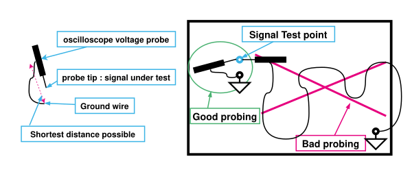
Voltage measurement must be performed with a dedicated oscilloscope probe, which must be compensated correctly. Most importantly, the ground connection must be the shortest possible, with the lowest impedance.
| The long ground wire increases the size of the loop and acts as an antenna to electromagnetic disturbances. Using a ground reference far from the signal test point, increase potential disturbances induced by current circulating in ground plane. |
2.2. Current probing
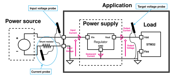
To measure current, a simple and efficient way is measuring voltage drop across a shunt resistor. Typically, a 1-ohm resistor drops 1 mV per mA. This technique is a low-cost one because it requires only a resistor and voltmeter.
This way, it is possible to capture current trace alongside supply voltage and other temporal signals with an oscilloscope.
The shunt resistor must be placed in series with the power supply and the load. It can be placed on the positive side, VDD, or negative side, GND.
| On many oscilloscopes, channels grounds are connected together. If so, all probs must be referenced on the same level. So, a good solution is to place a shunt resistor on a negative wire, reference all probs on the target ground and measure the negative voltage drop across the resistor by placing the probe on the power source side. This enables to use a tiny voltage scale and achieve better precision. |
3. Static measurements
The purpose of static measurements tests is verifying output voltage and current of the power supply in standard operation.
- Compare current
This test consists of running a power supply with low and high load currents to verify that the output voltage stays within the expected range. The goal is to gradually increase the load current to verify that the power supply regulates correctly with low and high currents. Run tests with different current consumption until the maximum consumption of the application.
3.1. Voltage too low
If the voltage drops below accepted tolerances at high currents, there are different causes possible:
- Current limit reached
- Reduce application current consumption.
- Increase the current limit or the power supply size.
- Power supply output impedance too high
- Wires, or PCB tracks, too long or too thin.
- Voltage ripple
- Voltage ripple, a periodic oscillation resulting from an instability of regulating loop of the power supply or the switching of the SMPS. The stability depends on the load current and the inductance and capacitance values. If the ripple exceeds anticipated levels, ensure that these component values and current align with the specifications outlined in the datasheet.
3.2. Voltage too high
If the voltage is above accepted tolerances, this is most likely a misconception:
- Wrong regulator reference.
- Wrong voltage divider for voltage regulator feedback.
4. startup phases
The power on sequence is the phase while the voltage is rising, and the components power on.
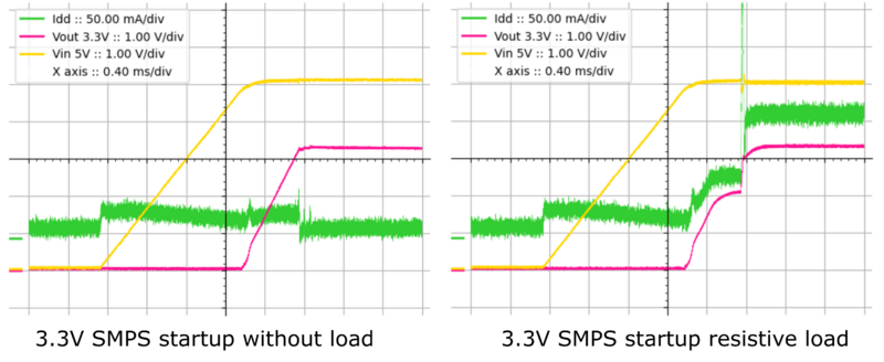
The application is often composed of multiple ICs, which might have different startup voltage and delays. It is a good option to have a quick voltage rising ramp to prevent too much delay between two components startup. Typically, ST Nucleo board power supplies rise in hundreds of microseconds.
It is better to start from below a few tens of mV with all circuits fully discharged with no residual voltages, see Power down sequence for more information.
The voltage curve must be monotonic and strictly rising.
During power on sequence, inrush current is most likely to cause issues.
- High consumption
Process to power up of application in various configurations, particularly the most power-intensive scenario expected during the product life cycle. The objective is to look at the inrush current and the profile of the voltage ramp.
4.1. Non-monotonic rising
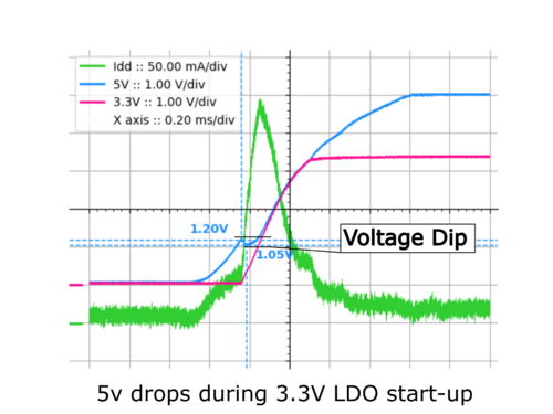
| Example: In this case, digital ICs are supplied by 3.3 V. The dip in 5 V is small and does not affect the microcontroller as it is compensated by the downstream 3.3 V LDO. |
During power-up, regulators and ICs start to operate at different voltage threshold and timing delay. These delayed current spikes can exceed the capacity of the power supply and temporarily induce a dip in the voltage. This is a sign that the limit of the system has been reached.
- Downstream regulator
- This behavior is often observed when a downstream regulator starts later. It draws as much current as possible to charge the circuitry. If it impacts too much the upstream power supply, a soft start might be required on the regulator to limit inrush current.
- Concurrent inrush current
- If multiple circuits draw a current spike at the same time, it might be a solution to delay reset signal release, to lower the magnitude.
4.2. Looping reset
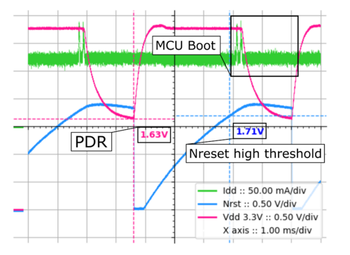
If the inrush current during the boot-up of digital ICs is substantial, it may cause the voltage to fall below the reset threshold. Consequently, the current diminishes, allowing the voltage to climb back above the reset threshold. This oscillation may occur repeatedly or potentially in a continuous loop.
| Example: In this scenario, the current limit feature is restricting the current flow. Upon release of the Nreset signal, the MCU boots, leading to a surge in current draw. If the power supply is unable to meet this demand, the voltage drops to the POR/BOR (Power-On Reset/Brown-Out Reset) threshold, triggering a reset. Consequently, the current draw decreases, allowing the voltage to recover. This cycle then repeats. |
4.3. Shutdown
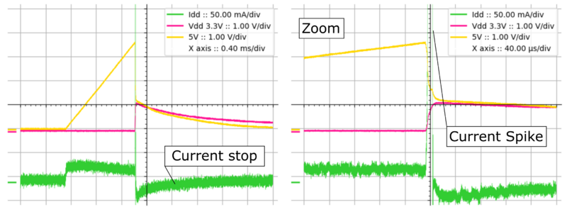
If a voltage drop and a complete cessation of current occur during power-up, it is likely that an overcurrent protection mechanism has been triggered.
| Example: In this case, the 5V supply rises, when the 3.3V regulator tries to start, is draws a current spike. This triggers the overcurrent protection of the 5V power supply. The current stops, or even reverses to discharge capacitors. |
4.4. Slow rise time
The rise of power supply can last longer than expected, especially with tight boot time requirements.
- Check the programmable soft start if the feature exists on the power supply
- If the soft-start feature is not responsible, this means that there is a mismatch between the power of the supply and the inrush current.
- Check current limit if exists on power supply.
- Check the total capacity of decoupling capacitors.
4.5. Startup order
On STM32, VDD must rise before other supply voltages. Look at voltage rails and make sure that boot orders are respected. Have a look at this section for more precision.
5. Transition phases
Once the power supply and application have started, voltage instability can be created by transient loads. The goal of these tests is to perform current transient and observe the power supply reaction.
Toggle between high and low current consumption configurations.
- Toggle power loads
The most significant transient is often external high-power loads. If the application has a load that consumes significant current, toggle these loads to perform current transient.
- Changing STM32 configuration
Changing internal configuration between the most and the less current consuming scenario expected during the product life cycle. The most impacting transitions are voltage scale (VOS) and clocks frequencies.
5.1. voltage dip
The main concern is voltage variations.
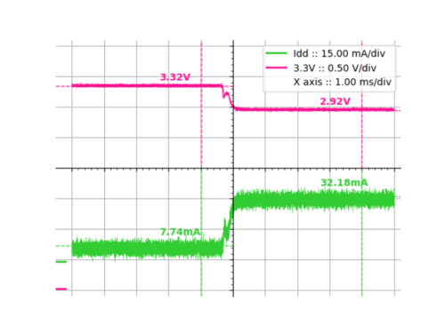
While the current increases, the voltage may drop, this is a voltage dip. If so, make sure that it stays within the fixed tolerances and above the minimum operating voltage and security threshold (POR/BOR).
Dip voltage can have multiple causes:
- Overloading power supply
- Note that it would have probably been discovered during previous tests, especially if peak current is lower than inrush current.
- Lack of decoupling
- Especially for high-speed transient, make sure to respect datasheets recommendations concerning decoupling.
- Power supply output impedance too high
- Wires, or PCB tracks, too long or too thin.
5.2. voltage swell
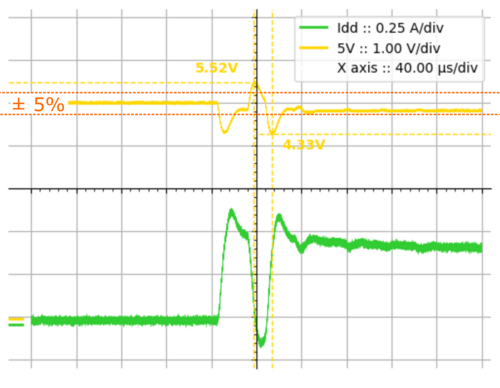
Especially during a drop of current consumption but also after a voltage dip, voltage swell occurs. Swells might lead to irreversible damage if it exceeds the operating voltages.
- Power supply control instability
- If the decoupling scheme is not properly implemented this might induce instability in the power supply. Make sure to respect the manufacturer datasheet.
- Serial impedance
- Wires add serial inductance, minimizing it helps to reduce parasitic voltage variations.
| Example: In this case, the toggle of a resistive load induces 520 mV swells and 670 mV dips, which is above the 5% typically accepted in industrial applications. |
5.3. Analog reference disturbances
If the application relies on the precision of analog peripherals, make sure that these voltage variations do not impact analog reference voltage.
6. Power down phases
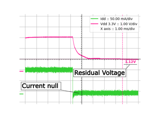
The importance of power down phase is often underestimated. It is recommended to always keep a low impedance tied on VDD, even for the power down phase. To properly discharge all capacitance, pull VDD below tens of millivolts with a low impedance.
Perform these tests during high current consumption phases and lowest current consumption. During these tests supply voltages and resets signals must be monitored.
Perform shutdowns in all the ways that the product can meet during its lifetime:
- Power source shut-down
- Unplug power source
- Soft power off
6.1. Residual voltage
If the voltage stays above tens of millivolts, the power supply output discharge does not work properly.
6.2. No reset
The reset should trigger (Nreset low) while the voltage drops below the BOR or PDR voltage. If not, the power supply supervisor does not work properly.
6.3. Wrong discharge order
On STM32 VDD must go down after other supply voltages. Look at voltage rails and make sure that shut down orders are respected. Look at voltage differences for more precision.
7. Conclusion
In summary, this article is a guide through a series of targeted diagnostic approaches to identify and understand potential power supply failures. By observing supply voltages and currents, common issues can be recognized and rectified, ensuring the reliable performance of the power supply. Remember that this article does not cover the complete process of power supply testing and validation.
