1. Introduction
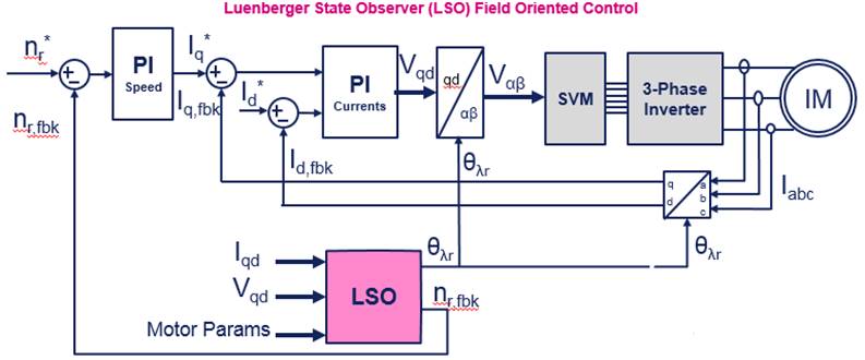
The demonstration firmware example projects for ACIM show how the STM32 MC SDK can be used to drive an asynchronous induction motor (ACIM) in field-oriented control (FOC) using a sensorless state observer algorithm to estimate the electrical and mechanical speed and position of the rotor and the rotor flux, or in V/F open-loop sensorless mode.
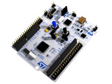
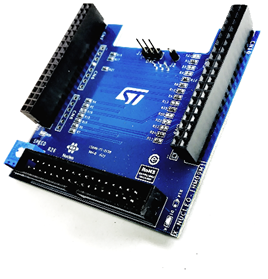
The provided application examples are intended to be used in a system composed of the NUCLEO-G431RB and the STEVAL-IHM023V3 boards, connected with the X-NUCLEO-IHM09M1 expansion board.
2. Main features
- STM32G4 Support of induction motors.
- Vector control algorithms:
- Self-sensing Field Oriented Control (LSO-FOC) (Sensorless)
- Scalar control algorithms:
- Open Loop V/f
- API function available to send the application commands to the motor driver using the STM32 MC motor pilot tool.
- PC GUI for firmware project update and dedicated induction motor parameters settings (ACIM GUI).
3. Hardware and Software setup
3.1. Hardware prerequisites
- 1x High voltage 3 phase motor driver board: (STEVAL-IHM023V3),
- 1x STM32 Nucleo development board: (NUCLEO-G431RB),
- 1x Motor control connector expansion board: (X-NUCLEO-IHM09M1),
- 1x DC power supply (max 400 Vdc),
- 1x USB type A to mini-B USB cable,
- 1x 3-Phase ACIM up to 1 kW.
3.2. Software prerequisites
- X-CUBE-MCSDK version 5.Y.*
- STM32 MC Motor Control Workbench 5.Y.*
- Only for the first example project generation.
- STM32CubeMx, version 6.2.0 or later
- STM32Cube MCU Package for STM32G4 Series, version 1.3.0 or later
- STM32 MC motor pilot v1.0 or later.
- STSW-LINK009: ST-LINK/V2-1 USB driver,
- STSW-LINK004: STM32 ST-LINK utility,
- Only to update ST-LINK firmware to the last version.
- A Windows PC with the supported development toolchain:
- IAR Embedded Workbench IDE – ARM
For more information, refer to the related documentation on STMicroelectronics website[1].
3.3. Field Oriented Control FW example for Induction Motors
3.3.1. Hardware configuration
- NUCLEO-G431RB
- Remove SB6. This disables LD2 but allows the use of DAC Ch2 on the PA5 pin for tuning or debugging.
- If the Nucleo board is powered by USB during the motor test with JP5 fitting pin 1 and 2, and in case of encoder sensor usage, connect a DC voltage source (7 to 12 V) on the VIN pin to provide the required E5V voltage to the MC_25 pin of the motor-control connector. For more information, refer to the document UM1724.
- X-NUCLEO-IHM09M1
- Remove R2, R3, R13, R18 R21, R22, R23 resistors.
- Stack the X-NUCLEO-IHM09M1 on the STM32 Nucleo board using the ST morpho-connector.
- Connect the X-NUCLEO-IHM09M1 to the STEVAL-IHM023V3 using the Motor control connector.
- Connect the STM32 Nucleo board to the PC through the USB cable.
- STEVAL-IHM023V3
- Set jumpers W1, W3, W5, W11 in 2-3 position.
- Set jumpers W9 and W13 in 3Sh position.
- Set jumper W14 Open.
- Set jumper W10 Closed.
- Check the board's user manual (UM1823) for more details.
3.3.2. How to use the STM32 MC firmware examples
- Open the related example files with the STM32 MC Workbench program:
- ACIM-NUCLEOG431RB-IHM023V3-VF_OL.stmcx, or
- ACIM-NUCLEOG431RB-IHM023V3-LSO_FOC.stmcx
- Save the file into another empty working folder. BEWARE: do not change the name of the .stmcx file, otherwise, the example will not work properly;
- Click on the Tool->Generation menu item. This pops up a dialog window that let the user select various parameters:
- Select version 6.2.0 or later for STM32CubeMX.
- Select your installed IDE version for IAR EWARM.
- Select STM32 FW V1.3.0 or later for the Firmware Package version.
- Make sure to check the box about the HAL usage for the Drive Type.
- Then, click on the UPDATE button.
- It is possible to configure further the generated project (for instance adjusting the motor parameters or the coefficients of the regulators) using the ACIMGUI present in the installation folder, under \Utilities\PC_Software\ACIMGUI.
- Once launched the ACIMGUI you have to select the .acimx file present in the generated project folder. According to the application needs, modify the parameters in the GUI and click the "update" project button.
- Do not use the STM32 MC WB anymore to generate the FW configuration, use instead the ACIMGUI.
- Open the generated project with the selected IDE;
- Build the project and load the resulting binary image into your MCU board;
- Reset your MCU board;
- Run the example
- Use the BLUE button on the board to start and stop the motor.
- Alternatively, the ST motor pilot.
The ACIM GUI therefore carries out the following tasks:
- Tuning of the PI controllers used by the motor control firmware.
- Update of the firmware project.
The next pages will explain how to use the ACIM GUI and the STM32 MC motor pilot, respectively, to configure the firmware, send commands to the motor, and perform the debug of the solution.
4. How to use the software tools
4.1. ACIM GUI
4.1.1. V/f Open loop mode
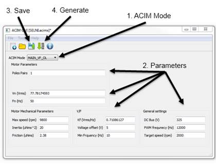
- The ACIM Mode dropdown menu helps to identify the main configuration of the ACIM firmware example. In this case MAIN_VF_OL mode. Do not change it. If you require to change this configuration, select the correct example project in the STM32 MC Workbench and generate a new working folder.
- Set the required parameters. (see Note 1)
- Save the project. Do not change the destination folder or filename.
- Click the Generate button.
Note 1:
- Ensure to avoid inserting letters in the numerical fields or not valid values, due to typing errors, to avoid undesired behavior of the motor and/or the hardware. The ACIMGUI does not perform any validity check on the inserted values.
4.1.2. Luenberger State Observer - Field Oriented Control (LSO-FOC) mode (without speed sensor)
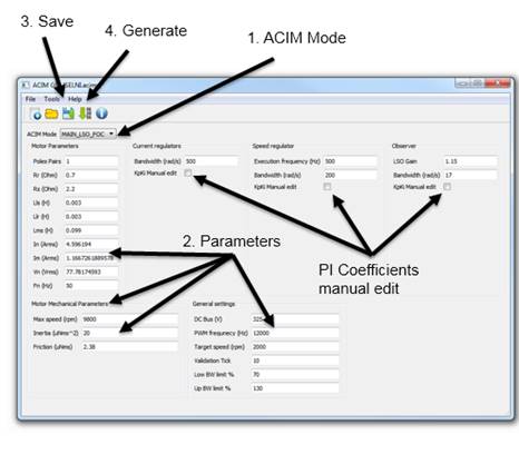
- The ACIM Mode dropdown menu helps to identify the main configuration of the ACIM firmware example. In this case MAIN_LSO_FOC mode. Do not change it. If you require to change this configuration, select the correct example project in the ST MC Workbench and generate a new working folder.
- Set the required parameters. (see note 4)
- Refer to Appendix A of this document to have more info about the measure of some parameters.
- Save the project. Do not change the destination folder or filename.
- Click on the Generate command.
- The project will be updated with the correct values of the gains (Kp and Ki) of the speed and current PI regulators.
- If the user intends to modify manually the gains can select the Manual Edit checkbox and adjust their value.
- In this case, make sure the divisors are a power of 2 to avoid compiling errors of the FW.
Note 4:
- Ensure to avoid inserting letters in the numerical fields or not valid values, due to typing errors, to avoid undesired behavior of the motor and/or the hardware. The ACIM GUI does not perform any validity check on the inserted values.
4.1.3. Information about the parameter to be inserted
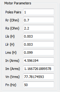
- Pole pairs is the number of rotor electromagnetic pole pairs.
- Rr is the rotor phase resistance expressed in Ohm.
- Rs is the stator phase resistance expressed in Ohm.
- Lls is the stator phase leakage inductance expressed in Henry.
- Llr is the rotor phase leakage inductance expressed in Henry.
- Lms is the rotor phase magnetizing inductance expressed in Henry.
- In is the rated nominal phase motor current expressed in amperes RMS.
- Im is the magnetizing phase current that corresponds to the no-load test phase current. In the case of FOC, it is the value fixed for Id current. It is expressed in amperes RMS.
- Vn is the rated phase to neutral voltage expressed in volts RMS.
- Fn is the rated motor frequency expressed in Hz.
- PWM frequency is the frequency of gate signals and of the high-frequency task, which manages the electromagnetic field angle computation and the duty cycle computation.
- Validation Tick is the number of consecutive Speed Loop task ticks when the measured Id current is into the [Low BW limit, UP BW limit] bandwidth. It is used at any startup to magnetize the motor before generating torque.
- Low BW limit and UP BW limit are the bandwidth limits and they are expressed in %
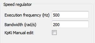
- Execution frequency of speed regulator section is the frequency of Medium Frequency task that manages the motor control state machine and then the speed loop execution.
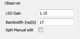
- LSO gain is the empiric value to set to guarantee the stability of the LSO (between 1-1.5).
- Target Speed is the default value that the speed control will take into account at the first Start Motor command; in this case, the user has not previously executed the Exec ramp command. (For more details of STM32 MC WB monitor window commands, refer to the dedicated slides of this document).
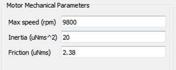
- Max Speed is the maximum mechanical speed that FW will allow to set as target speed. It can be chosen considering the minimum value between the maximum motor speed and the maximum speed readable by the sensor; or simply considering the max application speed, if it is not higher than the motor and sensor max velocity.
- Inertia is the rotor + load inertia coefficient.
- Friction is the rotor + load friction coefficient.
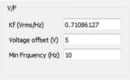
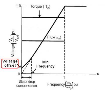
Kf (Vrms/Hz) Flux constant is the value of the flux maintained constant during the V/f control. The user can calculate it by dividing the nominal phase peak voltage by nominal frequency. If necessary, he can adjust to find the best value that provides the maximum torque with the maximum speed range according to the user’s application. Voltage offset is the peak value of voltage used to compensate the voltage drop on the stator winding at a very low frequency. (Below the Min Frequency). Min Frequency is used to fix the Voltage offset if the applied frequency is below the threshold.
The Bandwidth field is the PI regulator bandwidth used for its tuning. High values increase the reactivity of the regulator but can introduce noise and fast oscillation on the controlled quantity.
4.2. Real time comunication
4.2.1. ST motor pilot
Starting from the MCSDK 5.Y.0 version, the serial communication between the motor control firmware and the PC is managed with the STM32 MC motor pilot program.
The ACIM firmware examples are configured to use the STM32 MC motor pilot to send the basic commands like start and stop, set target speed, visualization, and clearing of fault conditions.
5. Appendix A - How to measure the motor electrical parameters with standard tests
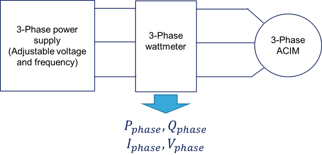
5.1. Measurement setup
5.2. Electrical model of the motor at steady state
Where:
| Parameter | Comment |
|---|---|
| R_s (Ω) | Stator phase winding resistance |
| L_ls (H) | Stator Leakage inductance |
| R_Fe (Ω) | Equivalent iron loss resistance |
| L_ms(H) | Magnetizing inductance |
| L_lr^'(H) | Rotor leakage inductance referred to stator |
| R_r^'(Ω) | Equivalent rotor phase resistance |
| Φ_n(Wb) | Nominal magnetizing flux |
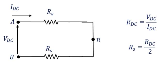
5.3. DC Test
During the DC test, a continuous electromagnetic field is generated. It means the equivalent impedance of the motor is resistive and only the stator has to be considered.
It consists of measuring the resistance between two stator windings with a multimeter.
5.4. No-Load test – Rotating test
No-load: slip s = 0 (ωre ≅ ωe)
Since I0 is equal to the magnetizing current, it is lower than the nominal current. In, the voltage drop on the Rs and Ls parameters is negligible concerning the nominal phase voltage, Vn. It is so possible to consider the following equivalent circuit:
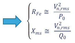
The term R_Fe represent the iron-losses and its value is higher than the magnetizing impedance module, Z_m= ω_e L_ms, so it is reasonable to consider, I_(m, RMS)≅ I_(0, RMS)
5.5. Blocked-Rotor test
The rotor is mechanically blocked: slip s = 1 (ωre = 0)
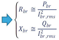
Since I_br is equal to I_n and is higher than the magnetizing current (no-load current), I_br, (I_br >> I_m) the magnetizing branch is negligible in respect of the series one. It is so possible to consider the following equivalent circuit:
6. Appendix B - Block diagrams and principles about the implemented ACIM control methods
6.1. Legend of symbols
- fe = stator frequency, Hz
- ωe = stator pulsation, rad/s
- ωre = rotor electrical pulsation, rad/s
- ωslip = slip pulsation, rad/s
- n*r = mech. target speed, rpm
- nr,fbk = mech. target speed, rpm
- τr = Lr/Rr = electrical rotor time constant, s
- I*qd = q-d reference frame reference current vector
- Iqd,fbk = q-d reference frame measured current vector
- Vqd = q-d reference frame voltage vector
- Vαβ = α-β reference frame voltage vector
- θλr = rotor flux position
6.2. Constant airgap flux operation - V/f
6.2.1. Open loop block diagram
Advantages
- Simple control.
- No speed sensors.
- Motor electrical model not required.
Drawback and Limitations
- Low efficiency.
- Low control dynamics.
- No speed control.
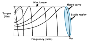
- Although the stable region curve slope remains constant, maintaining the V/f = const., an increase/decrease of the mechanical load causes a variation of the rotor speed (modifying the slip frequency to provide the required torque).
6.3. Field Oriented control
6.3.1. Luenberger State Observer–FOC (LSO-FOC) – solution without speed sensor
Advantages
- High efficiency.
- High control dynamics.
- Speed sensor not required both for rotor flux position estimation and for speed loop execution.
Drawback and Limitations
- Motor electrical model is required.
- Motor parameters variation dependency (i.e. variation of resistances with the temperature) badly affecting the efficiency and/or the speed estimation accuracy.
- Complexity of estimator model.
- Empiric setting of the observer gain.
7. References

