1. Introduction
The STM32 motor control (MC) software development kit (SDK), is part of the STMicroelectronics motor-control ecosystem. It includes:
- ST MC FOC FW library for permanent-magnet synchronous motor (PMSM) field-oriented control (FOC)
- ST MC 6-Step FW library
- ST Motor Profiler
- ST Motor Pilot
- ST MC Workbench software tool, a graphical user interface (GUI) for the configuration of MC SDK firmware library parameters
This document explains how to use the ST MC Workbench software tool included with this MC SDK.
2. General information
The ST MC Workbench software tool provides you with an easy and friendly way to configure your MC application software matching your hardware setup.
When done, the user can generate directly its project, which is compatible with the STM32CubeMX usage for a further MC application extension.
The ST MC Workbench runs on PC systems, using Windows® OS, and requires a USB type A connector.
3. The ST motor control Workbench
Launch the "ST motor control Workbench" software tool by clicking either its icon (see figure 1: ST MC Workbench–Icon) or running directly from the installation folder.
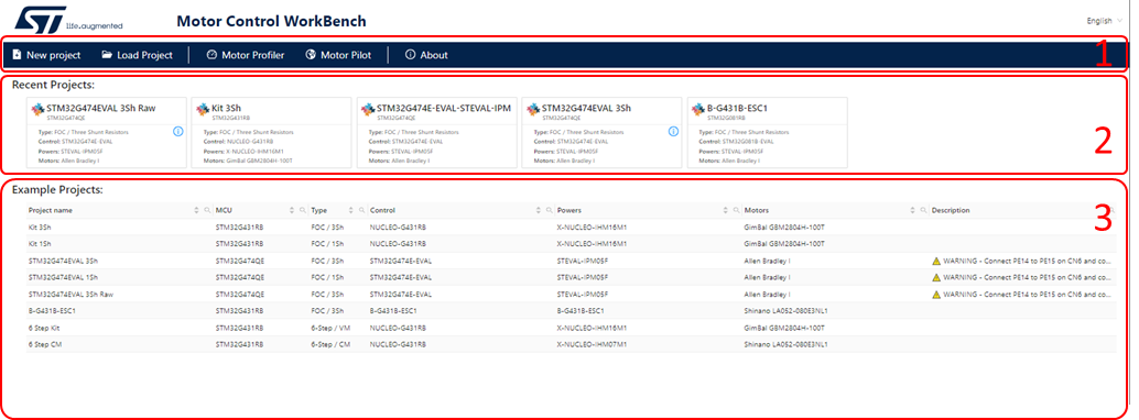
The ST MC Workbench GUI presents the following home area (startup page) where there are the following sections:
- The user buttons area (Id. 1 in Figure 2: ST MC Workbench – GUI (Home View)) to start either a new project or load a previous one, as well as launching the ST Motor Profiler or Motor Pilot software tools.
- The Recent projects area (Id. 2 in Figure 2: ST MC Workbench – GUI (Home View)) to load a user recent project.
- The Examples projects area (Id. 3 in Figure 2: ST MC Workbench – GUI (Home View)) to load a project example.
3.1. Editing field behavior
One of the commons developing path in the ST MC Workbench is the editing and combo field behavior. Each edit or combo field has the following format and behavior:
- Label area: in this area the field name is shown with optionally a number notification bullet that shows specific notes on field. The bullet should be info (blue), warning (orange) or error (red) and the specific messages pop-up on bullet mouse over.
- Editing area: in this area the user can set its own value. The field (edit or combo) assumes different styles depending on its editing state:
- Field with default value, no value specified by user (value in light grey). The default value can be changed silently by the application itself.
| Edit fields | Combo fields |
|---|---|
- Field with default value in editing mode (value in light grey). The user can edit its own value. The user can transform the default value in explicit user value clicking on the upper-right small icon (
 ).
).
| Edit fields |
|---|
- Field with explicit user value (value in black). The explicit user value cannot be recalculated by the application. The user can reset the field to its default value pressing the upper-right small icon (
 ).
).
| Edit fields | Combo fields |
|---|---|
- Field with error on value (value in red). The user must review the field or reset the field to its default pressing the upper-right icon.
| Edit fields | Combo fields |
|---|---|
Unit and legend area: this area is optional; it indicates the unit and/or the legend of the field (i.e., valid range).
3.2. New Project wizard
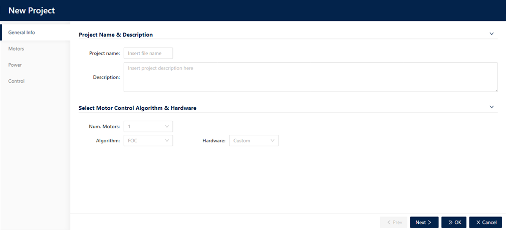
When clicking on the “New Project” button (see Figure 2: ST MC Workbench – GUI (Home View)), a window pops-up that help the user to define step by step the project configuration (see Figure 4).
3.2.1. General Info
In the General Info step the user can set the following info:
- “Project Name & Description”
- Insert a “Project name” (optional field), if specified it will be used as default file name in “save as…”.
- Insert a “Description” (optional field).
- “Select Motor Control Algorithm & Hardware”
- Selects “Num. Motors” usage.
- Selects “Algorithm” Type (that is, FOC, 6-Step…).
- Selects your ST “Hardware” type boards:
- “Custom” If your system is composed of a control evaluation board together with a power evaluation board.
- “Kit” if your ST board is an ST MC Kit (that is, P-NUCLEO-IHM003).
- “Inverter” if your ST board is a complete inverter board (single board with both power and control electronics).
3.2.2. Motors
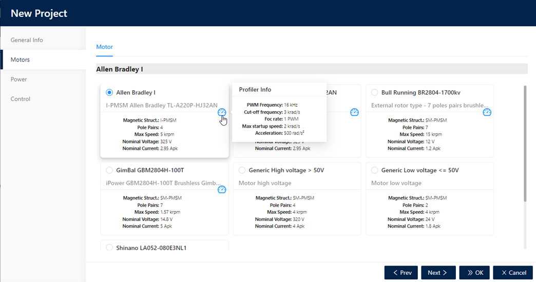
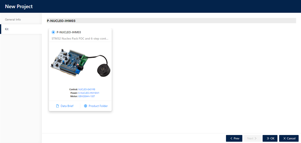
In the Motors step the user selects the motor to use in the project. The user can select a “Generic Motor” or a “Profiled Motor”; the “Profiled Motor” is identified by an icon ![]() (see example from Figure 5: ST MC Workbench – New Project window – Motors). This step is not available in case the user selects as “Hardware” a ST MC Kit (see example from figure 9: ST MC Workbench – New Project window – Kit). The list provides a set of motors delivered with the application as well as the user motors.
(see example from Figure 5: ST MC Workbench – New Project window – Motors). This step is not available in case the user selects as “Hardware” a ST MC Kit (see example from figure 9: ST MC Workbench – New Project window – Kit). The list provides a set of motors delivered with the application as well as the user motors.
3.2.3. Power board
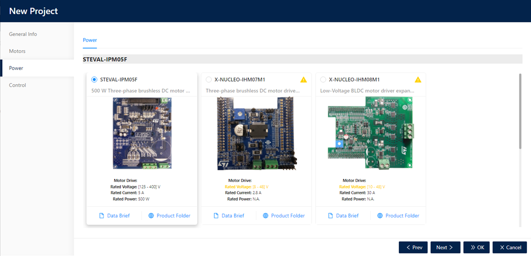
In the Power step, a list of available power boards is shown. The power boards are sorted by the compatibility with the motor supply (previously selected). A yellow triangle (as warning) shows if the board-output power supply is not properly compatible with the motor.
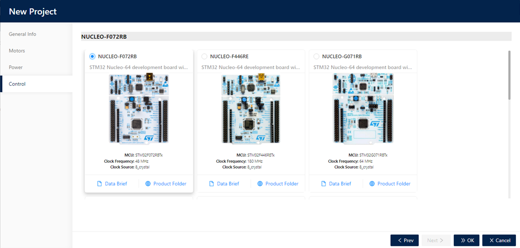
3.2.4. Control board
In the Control step a list of supported control boards are proposed. The list is sorted by compatibility with the power selected. An extra step (Bridge) is shown if the connector from power and control is not compatible and need an adapter board.
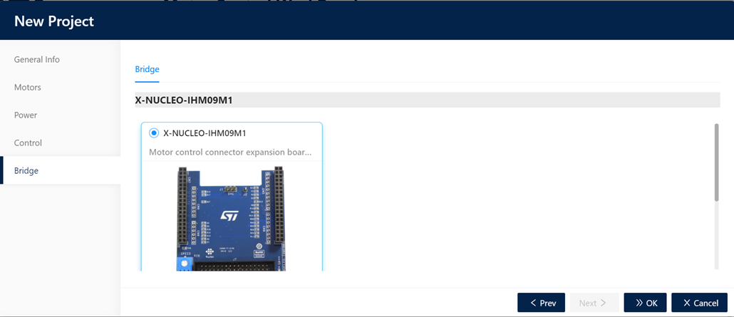
3.2.5. Bridge
In the Bridge step, a list of available adapters are shown for selection. The bridge selection allows the usage of boards (power and control) that are not directly connectable because they have different connectors. These are morpho and motor control connectors).
3.2.6. Kit
The Kit step allows the selection of available supported kits. A “kit” is a set of control board, power board and motor.
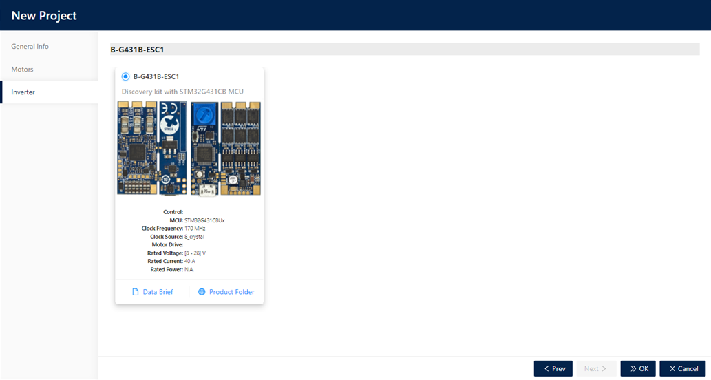
3.2.7. Inverter
The Inverter step allows the selection of available inverters. “Inverter” is a complete board (single board with both power and control parts).
3.2.8. Creating the project
At the end of the New Project wizard, the user can click on the “OK” button to create the project. The hardware must be correctly selected by the user and depends on the hardware type field.
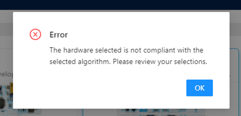
A post selection procedure is executed to check if the configuration allows the creation of the project. If the user selection is not valid, a dialog pops-up to inform the user that the choices do not allow the project creation. It then ask to refine these choices (see Figure 11: ST MC Workbench – New Project creation error).
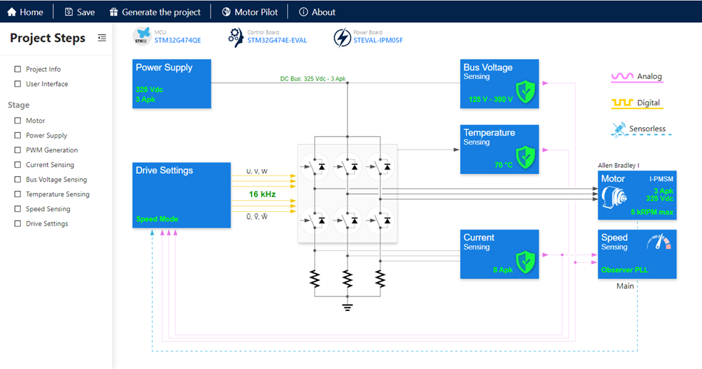
Otherwise, the user selection is valid, and a Motor Control Project will be created, and the project view (see Figure 12: ST MC Workbench – Project view) will be shown with all the information that depend on the selected boards and motor.
3.3. Loading an existing Project
When clicking on the “Load Project” button (see id 1 Figure 2: ST MC Workbench – GUI (Home View)), a system dialog window will be shown and the user can select the project file to load (.stwb6). Loaded Project will be shown in the “Project view” (see Figure 13) where the user can refine it.
3.4. Project view
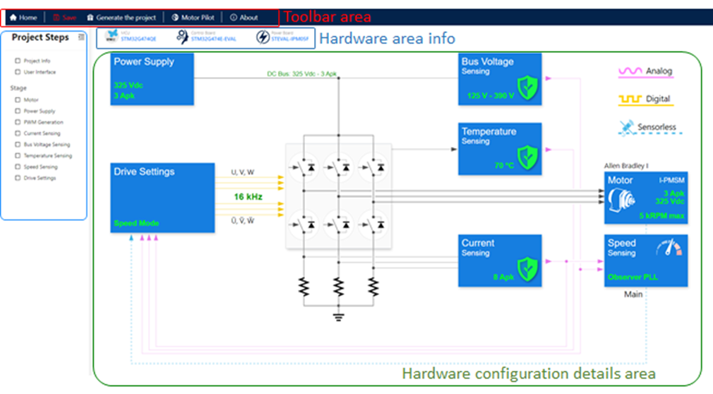
The project view is composed by:
- Toolbar area
- Hardware area info
- A Project Steps area to select your hardware part to parametrize:
- Motor
- Power Supply
- PWM generation
- …
- Hardware configuration details are: used to fine-tune the selected hardware functionality and to view all the main info and protection at a first glance.
3.4.1. Toolbar area
The toolbar area is useful to control application navigation, project saving and generation.
3.4.1.1. Home
Clicking on ![]() provides the user, with an easy way, to close the current project and came back on home view (see Figure 2: ST MC Workbench – GUI (Home View)). When not already saved, a confirmation window pops-up (see Figure 14) asking the user either to save or not the current project . It also ask to cancel the action, then it goes back to the hardware configuration window (see Figure 13).
provides the user, with an easy way, to close the current project and came back on home view (see Figure 2: ST MC Workbench – GUI (Home View)). When not already saved, a confirmation window pops-up (see Figure 14) asking the user either to save or not the current project . It also ask to cancel the action, then it goes back to the hardware configuration window (see Figure 13).
3.4.1.2. Save
Clicking on ![]() presents the Save menu.
presents the Save menu.
- Save: save user current project;
When not already saved, a file manager window pops-up to save user current project as a new one (see figure 16).
- Save as… save user project as new one file;
A file manager window pops-up to save user project as a new one (see figure 16).
3.4.1.3. Generate the project
Clicking on ![]() , generates the user application project files. If the project file not already saved, an information window pops-up to indicate that this project needs to be saved before to generate. Use the “Save & Generate” button to save and generate.
, generates the user application project files. If the project file not already saved, an information window pops-up to indicate that this project needs to be saved before to generate. Use the “Save & Generate” button to save and generate.
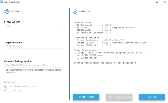
A window pops-up (see Figure 18: ST MC Workbench – Project generation) to allow the user to select target toolchain, firmware package version, drive type and generate the Motor Control firmware application throw the selected STM32CubeMX.
3.4.1.4. Motor Pilot
Clicking on Motor Pilot toolbar button the Motor Pilot application will be launched.
3.4.1.5. About
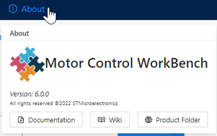
Clicking on the "About" menu window pops-up some application information and useful links.
3.4.2. Hardware information area
The hardware information area presents hardware information of the current project.
3.4.2.1. MCU - Pin usage and conflicts
Moving over MCU a window pops-up will be shown (see Figure 20: ST MC Workbench – MCU):
- Product Folder
- Clicking on it, the Product Folder page for the MCU selected will be open.
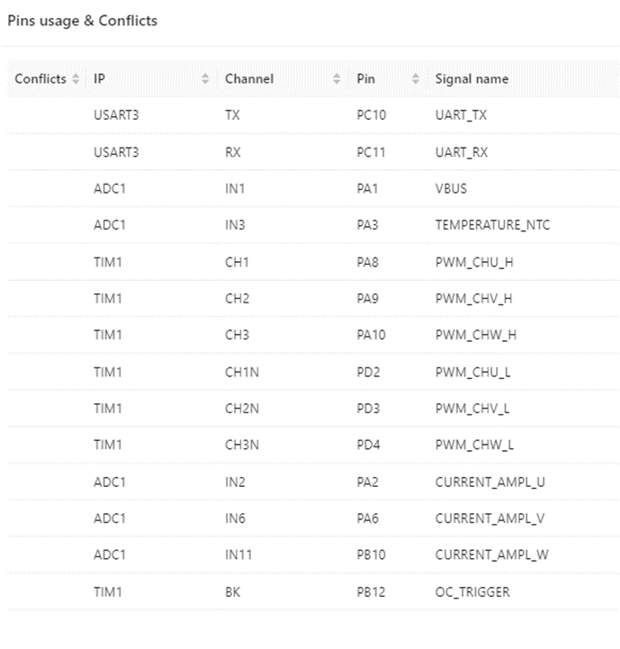
- Pin usage & Conflicts
- To control the pin assignment of the MCU and receive feedback about the pin conflicts (see Figure 21).
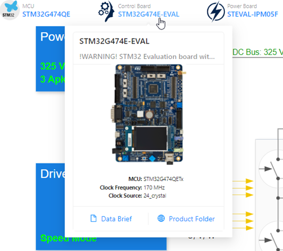
3.4.2.2. Control Board
Moving over![]() Control Board a window pops-up give general information about the control board selected and it shows:
Control Board a window pops-up give general information about the control board selected and it shows:
- Data brief folder
- Clicking on it, the relative data brief page opens.
- Product Folder
- Clicking on it, the relative Product Folder page opens.
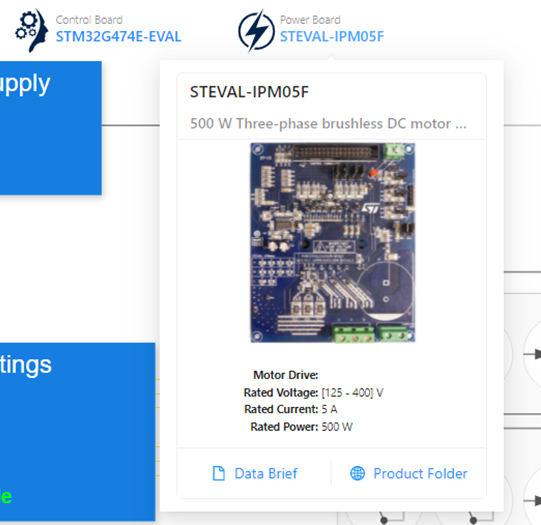
3.4.2.3. Power Board
Moving over  Power Board a window pops-up give general information about the power board selected and shows:
- Data brief folder
- Clicking on it, the relative data brief page opens.
- Product folder
- Clicking on it, the relative product folder page opens.
3.4.3. Project steps and hardware configuration details
All the hardware configurations alternatives depend on the hardware selected and are accessible from the wizard steps. The wizard steps are available from the left application panel (Project Steps area) as well as from the hardware configuration details area (main project view) clicking on the boxes. The information shown in the schematic are aligned with the wizard steps choices.
3.5. Project wizard
The project wizard is accessible from the left panel items or from the relative main schematic view. When clicking on one of these items, the full wizard pops-up and the relative step is shown. The wizard is customized depending on the selected algorithm and in any case all the steps are available, and the user can move over all of them. The project wizard is the smart way to customize and configure the motor control application for the hardware selected. Each wizard step contains several checks and information that help the user to make right configurations. in case of errors the wizard doesn’t allow the project update and ask the user to fix the errors before applying the changes. In any case if there are errors, the firmware project generation is not allowed.
The step sequence on the wizard has a special meaning: The values of a field on a step can depend only on fields on previous steps and not for the forward steps. The field sequence dependency is also followed inside each step. It is from top to bottom and from left to right.
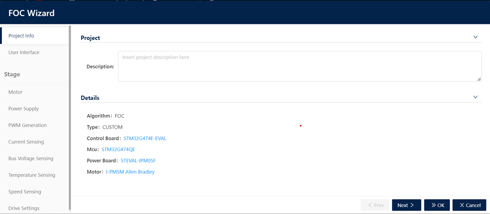
3.5.1. Project Info
This is a common step where the user can set the project description, to better identify the project, specifying project characteristics and extra user information. The project description is also visible as a small pop-up icon in the recent project list (Id. 2 in Figure 2: ST MC Workbench – GUI (Home View)).
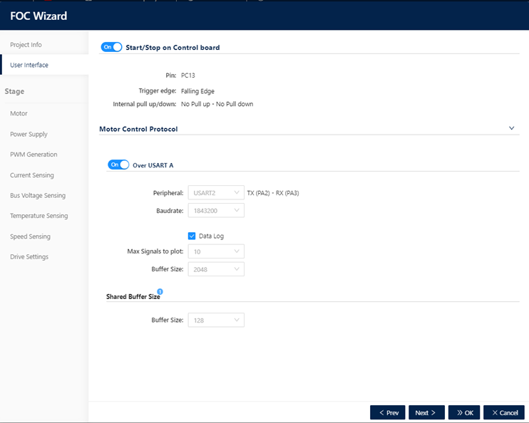
3.5.2. User Interface
This is a common step where the user can configure “Start and Stop button” and the “Motor Control Protocol (MCP)”, if these features are available for the hardware selected.
The user can change only the configurations that are available for the specific hardware selected. In the case shown in the above image, the start/stop is available only on PC13 pin. If the hardware selected allows more possibilities a combo will be available to allow user to select the right pin to use. The Start/Stop feature can be disabled if the user does not want to use it.
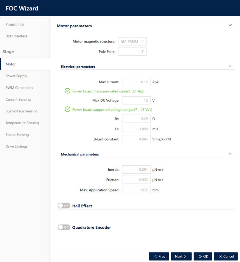
3.5.3. Motor
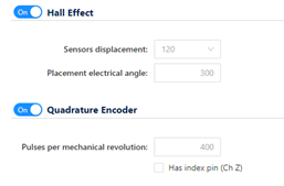
This step is relative to the Motor parameters. The default values are loaded from the selected motor during the creation of the project (see Figure 5: ST MC Workbench – New Project window – Motors). The user can modify each motor parameters (see Figure 26: ST MC Workbench – Motor) and activate and configure Hall sensor or Quadrature Encoder for the used motor (see Figure 27: ST MC Workbench – Motor – Hall Effect – Quadrature Encoder).
3.5.4. Power Supply
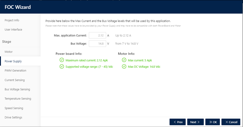
In this step, the maximum current and the bus-voltage levels that are used by the application can be set. The values in this step must be the one provided from the power supply and must be compatible with the power board and motor.
3.5.5. PWM Generation
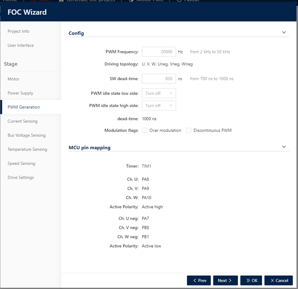
In this step the user can select PWM, driving topology available for the selected hardware, PWM frequency, modulation flags and the MCU pin configuration for the topology used. For different driving topology different configurations are available.
3.5.5.1. High and low side topology
The following image shows the step for high and low side driving topology.
3.5.5.2. High side and three enables topology
The following image shows the step for high side and three enables driving topology
3.5.6. Current sensing
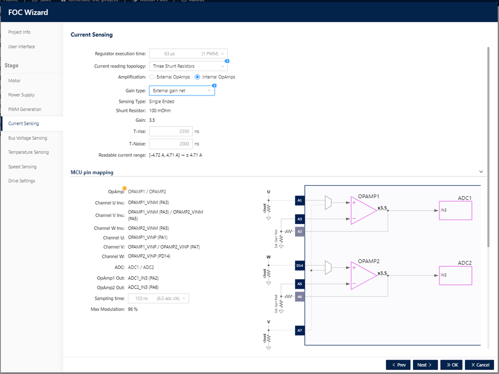
In this step, the user can select the available current reading topology and amplification (see Figure 31: ST MC Workbench – Current Sensing). Depending on topology, amplification and gain, the user is prompted with the relative fields to set and MCU Pin for that configuration, a schema will show the configuration selected in a graphical way. The information on the step depends also on algorithm selected (FOC or 6 Step).
3.5.6.1. FOC 3 Shunt External Amplification
In this Current Sensing topology, the user can set Regulator execution time, the T-Rise and T-Noise. The current amplification in this case is done in the power board. The following image shows the configuration.
3.5.6.2. FOC 3 Shunt Internal Amplification – Internal Gain
In this Current Sensing topology, the user can set regulator execution time, the internal PGA gain factor, the T-Rise, and T-Noise. In this case, the current amplification is done using internal MCU OpAmp. The following image shows the configuration.
3.5.6.3. FOC 3 Shunt Internal Amplification – External Gain
In this Current Sensing topology, the user can set Regulator execution time, the T-Rise and T-Noise. In this case, the current amplification is done using internal MCU OpAmp. The gain depends on the gain net in the control board. The following image shows the configuration.
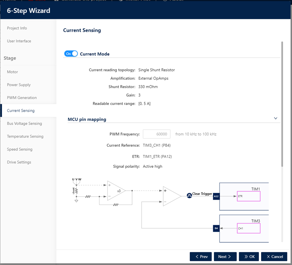
3.5.6.4. 6 Step Current Mode
This is available only for 6-Step algorithm. The user can enable/disable Current mode. The current mode can be enabled only if the feature is available for the hardware selected (see Figure 34: ST MC Workbench – 6 Step – Current Mode). By default, the Current Mode is disabled (C.f. Figure 35: ST MC Workbench – 6 Step – Current Mode disabled).
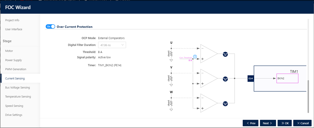
3.5.6.5. Over-current protection
From the current sensing step, the user can enable and configure also the over-current protection (OCP) (see Figure 36: ST MC Workbench – Current Sensing – Over Current Protection); the settings depend on the available OCP mode for the selected hardware. A "generic" schema shows the hardware connections between the signals and the MCU.
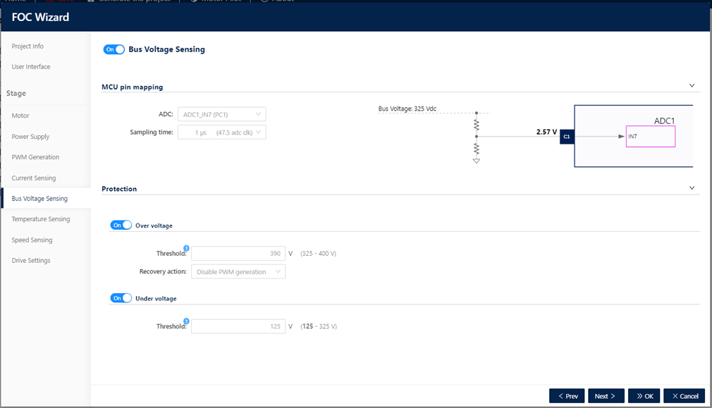
3.5.7. Bus voltage sensing
In the bus voltage sensing step, the user can configure the sensing of bus voltage (if available for the hardware specified) and the relative Over Voltage and/or Under Voltage protection.
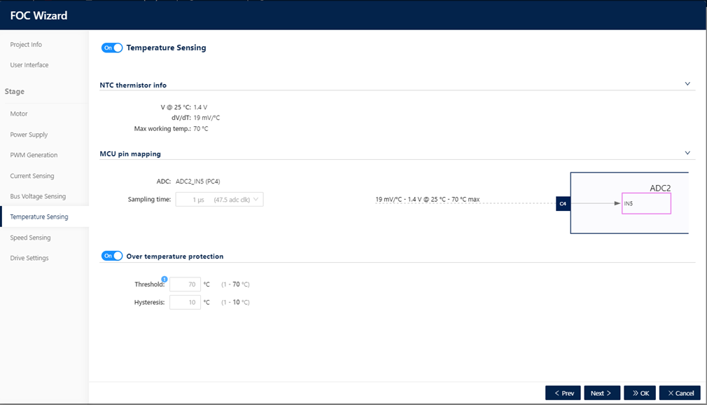
3.5.8. Temperature Sensing
In the Temperature Sensing step, the user can configure the sensing of temperature (if available for the hardware specified) and the relative Over Temperature protection.
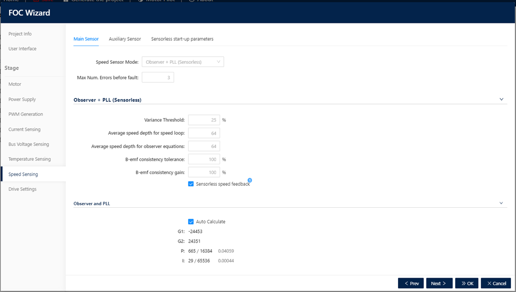
3.5.9. Speed Sensing
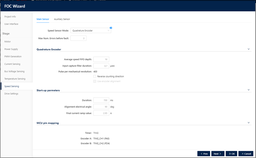
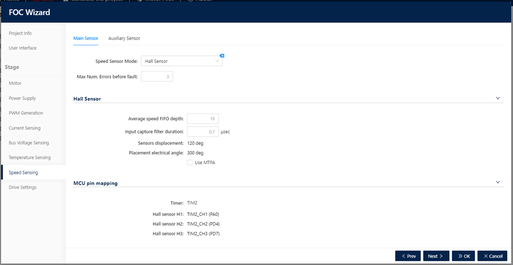
In the Speed Sensing step, the user can select the speed sensing to use; there are different speed sensing modes that are available for both Main and Auxiliary Sensor. Auxiliary sensor is optional, by default disabled. The Speed Sensing modes depend on the selected algorithm (FOC or 6 Step).
3.5.9.1. FOC Observer + PLL (Sensorless)
This speed sensing mode is the default for the main sensor, it is always available.
3.5.9.2. FOC Observer + Cordic (Sensorless)
This speed sensor mode is always available.
3.5.9.3. FOC Quadrature Encoder
This speed sensor mode depends on hardware availability and motor capability. The motor must have the sensor enabled and the feature must be supported by the hardware.
3.5.9.4. Hall Sensor
This speed sensor mode depends on hardware availability and motor capability. The motor must have the sensor enabled and the feature must be supported by the hardware. This speed sensor mode can be used in FOC and 6 Step algorithm.
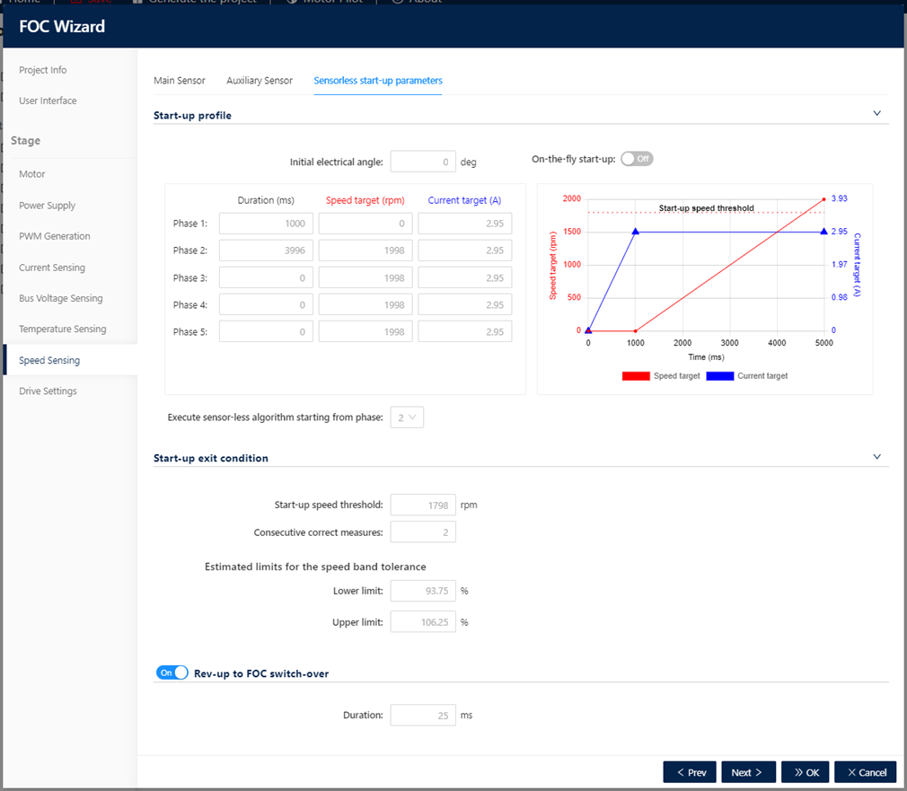
3.5.9.5. FOC Sensorless Start-up parameters
The settings of the “Sensorless Start-up parameters” are available only if the main sensor selected is a sensor less (Observer + PLL or Observer + Cordic).
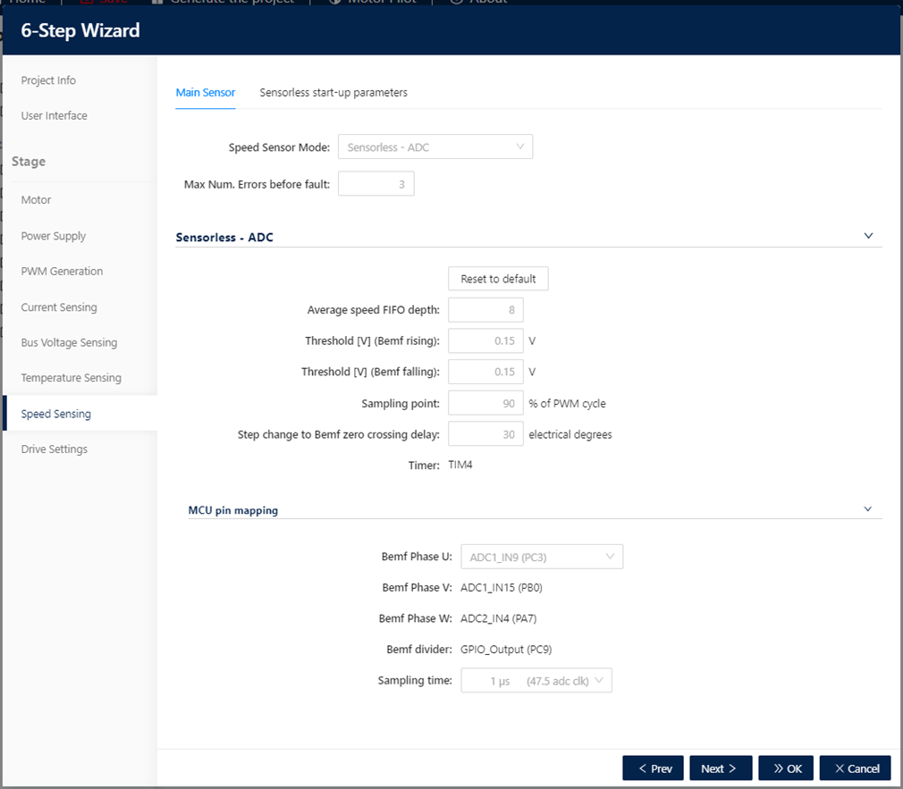
3.5.9.6. 6 Step Sensorless ADC
Sensorless – ADC is a specific Speed Sensing mode for 6 Step algorithm (see Figure 44: ST MC Workbench – 6 Step – Sensorless ADC).
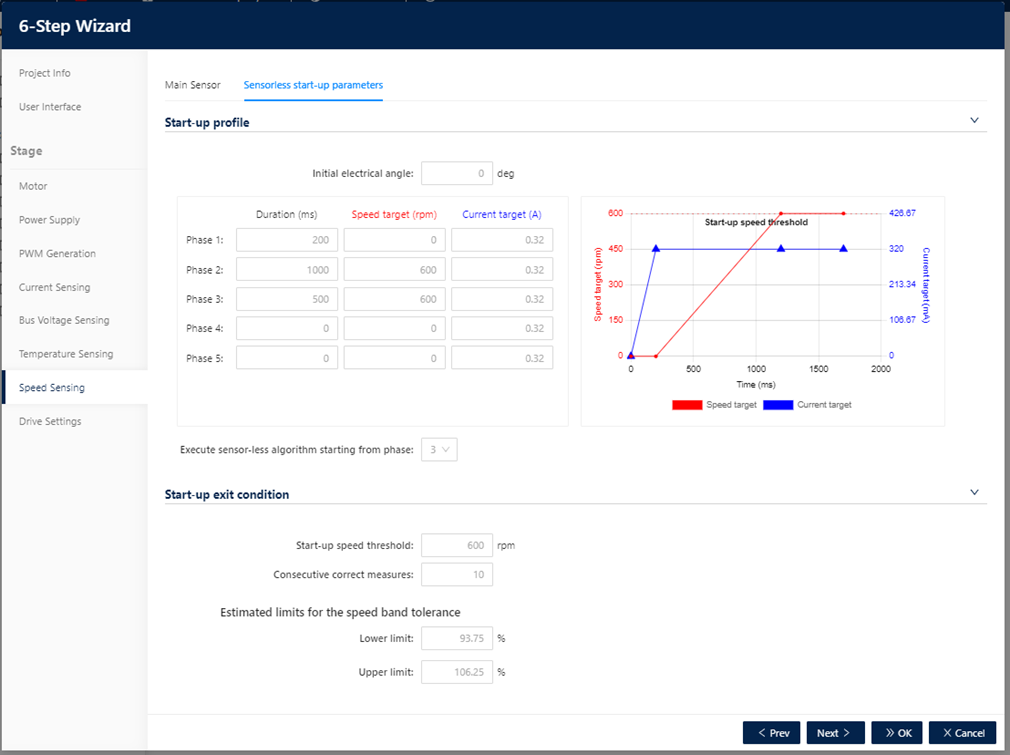
3.5.9.7. 6 Step Sensorless Start-up parameters
6 Step algorithm has specific “Sensorless Start-up parameters” settings, available if Speed Sensing mode selected is Sensorless-ADC.
3.5.10. Drive Settings
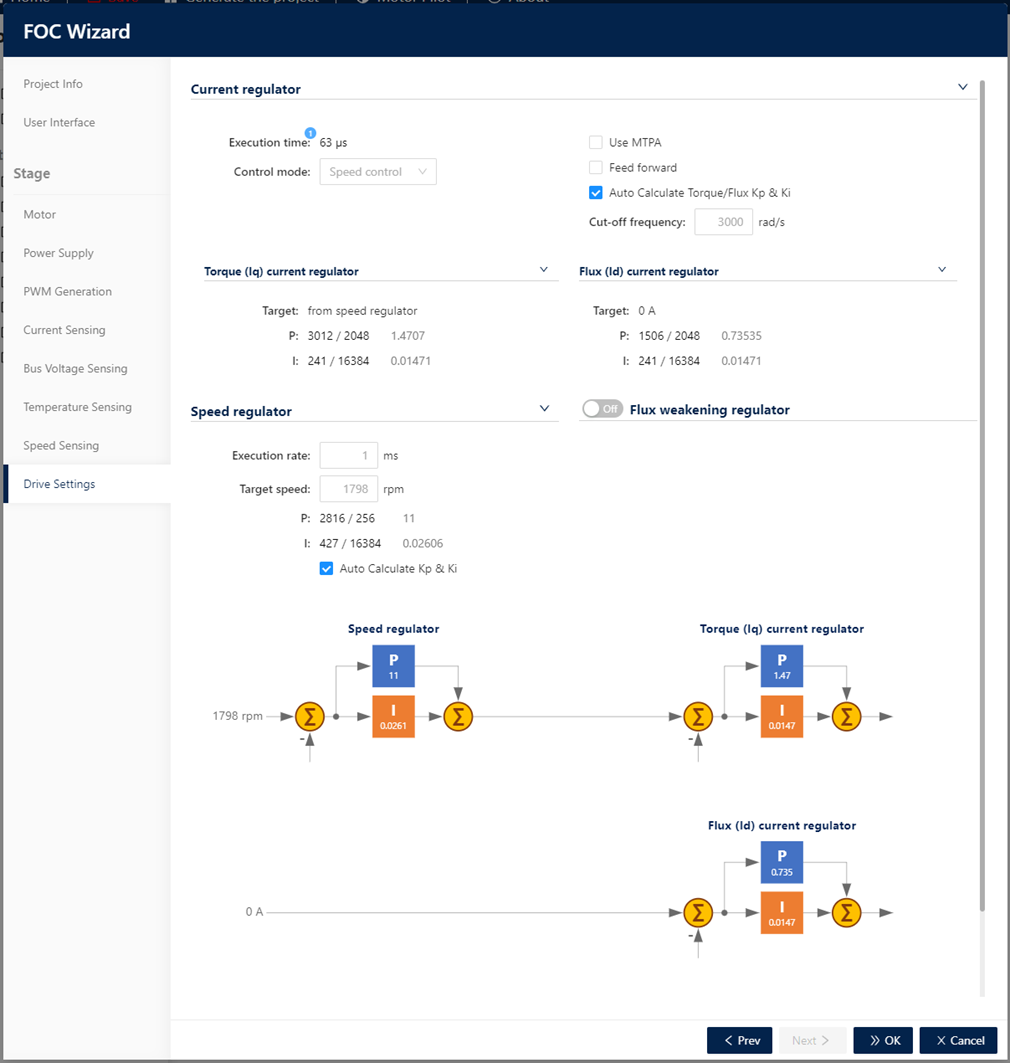
In the Drive Settings step, the user can configure current regulator as one of the following three control mode.
3.5.10.1. Speed control
This drive settings mode is always available.
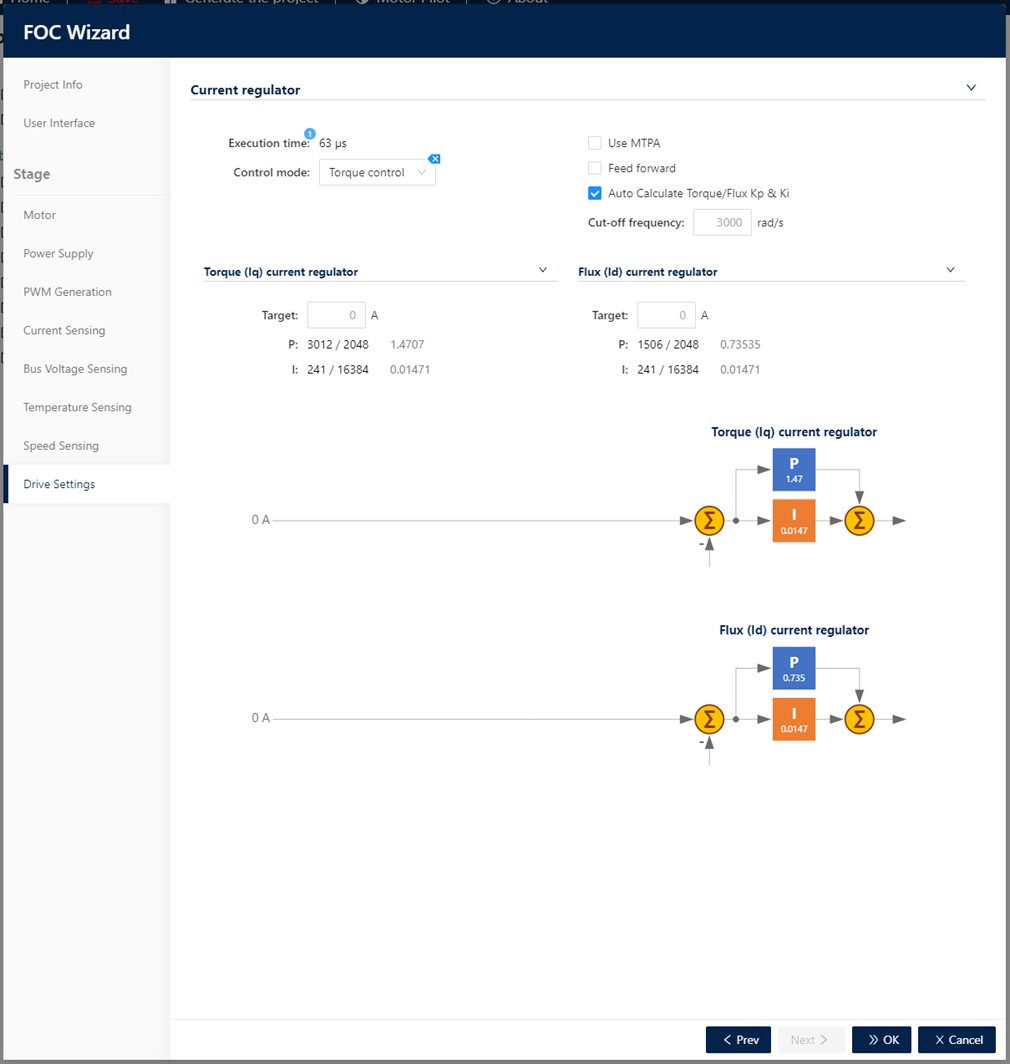
3.5.10.2. Torque control
This drive settings mode is always available.
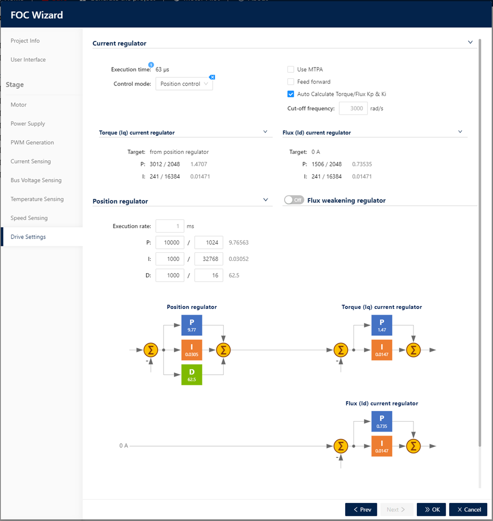
3.5.10.3. Position control
This drive settings mode is available only if Quadrature Encoder is selected as main Speed Sensing sensor.
[[Category:Motor Control]]
