This article explains how to get started on the Face Reco face recognition application running on the STM32 microcontroller. The face recognition application is capable of recognizing a user's face among those of enrolled users.
This article provides an overview of the following topics:
- Overview of the required hardware setup
- Overview of the software architecture
- Description of the Face Reco application running on STM32
1. Hardware setup
The Face Reco application is running on a hardware setup made up of an STM32 microcontroller board connected to a camera module board.
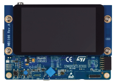
1.1. STM32 board: STM32H747 Discovery Kit
The STM32H747I-DISCO is a complete demonstration and development platform for STMicroelectronics STM32H747XIH6 microcontroller, designed to simplify user application development. The STM32H747XIH6 device is based on the high-performance Arm® Cortex®-M7 and Cortex®-M4 32-bit RISC cores. The Cortex®-M7 core operates at up to 480 MHz and the Cortex®-M4 core at up to 240 MHz.
The STM32H747XIH6 device incorporates high-speed embedded memories with a dual-bank Flash memory of 2 Mbytes and of 1 Mbyte of RAM.
The other key specifications of the board are:
- On-board STLINK-V3E debugger/programmer
- USB OTG HS
- 4” capacitive touch LCD display module with MIPI® DSI interface
- 2 x 512-Mbit Quad-SPI NOR Flash memory
- 256-Mbit SDRAM
- 8-bit camera connector
- microSD™ card
1.2. Camera board
In the context of the Face Reco application, the firmware supports the two following camera sensors:
- The OV5640 sensor
- The OV9655 sensor
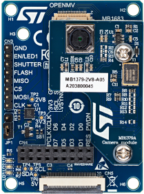
The recommended camera setup is the B-CAMS-OMV bundle for STM32 boards. Module boards are supported.
The B-CAMS-OMV bundle is made up of:
- One camera module adapter board (MB1683)
- One STMicroelectronics camera module (MB1379), based on the OV5640 image sensor offering a 5-Mpixel resolution with 8-bit color
- One flexible flat cable (FFC)
The picture below shows the B-CAMS-OMV without FFC:
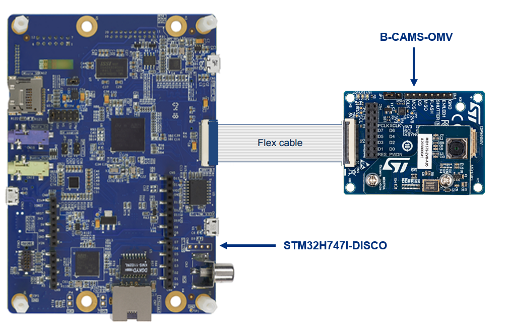
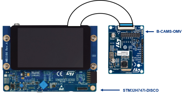
1.3. STM32H747I-DISCO connection to camera boards
The picture below shows how to connect the camera board to the STM32H747I-DISCO board using a flat flex cable:
2. Software architecture
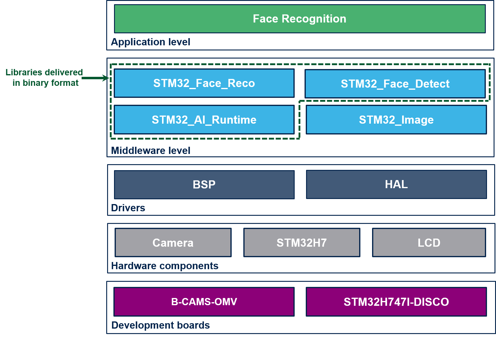
The figure below depicts the software architecture of the face recognition application:
Here is below a brief description of the middleware components:
2.1. STM32_AI_Runtime
This is an STM32 optimized AI library generated by the X-CUBE-AI tool when generating the C neural network model.
2.2. STM32_Image
This is a library of functions for image preprocessing, such as rescaling or pixel format conversion.
2.3. STM32_Face_Detect
Library containing functions for face detection purpose.
2.4. STM32_Face_Reco
Library containing functions for face recognition purpose.
3. Description of Face Reco application
The figure below shows the different frame processing stages involved in the face recognition application:
3.1. Camera capture
The camera frame capture has the following characteristics:
- Resolution is set to QVGA (320 x 240)
- Pixel color format is set to RGB565
3.2. Frame Preprocessing
The main preprocessing stage involved in the Face Reco application is the pixel color format conversion so to convert the RGB565 captured frame into a RGB888 frame.
3.3. Face Detection
The Face Detection block is in charge of finding the faces present in the input frame (QVGA, RGB888). In the current version of the application, the maximum number of faces that can be found is set to one. The output of this block is a frame of resolution 96 x 96 that contains the face found in the input captured frame.
3.4. Face Recognition
The Face Recognition block is in charge of extracting features from the face and computing a signature (embedding vector) corresponding to the input face.
3.5. Face Identification
The Face Identification block is in charge of computing the distance between:
- The vector produced by the Face Recognition block, and
- Each of the vectors stored in memory (and corresponding to the enrolled faces)
The output Face Identification block generates the two following outputs:
- a User Face ID corresponding to the minimum distance
- a similarity score
4. Running the application
The application has two main operating modes:
- The "nominal" mode
It is the default operating mode during which the application is attempting to match the face contained in the input frame with a specific User Face ID.
- The "enrollment" mode
Prior to being able to link a face with a User Face ID, the system must have the User face ID recorded into its database. For that purpose, a user must enroll himself to have his face features (in the form of a feature vector) recorded into the memory.
Note that the current version of the Face Reco application does not support the retention of the enrolled users. In other words, all the enrollment information are lost upon reset.
Practically, here is how it works:
4.1. Nominal mode
Upon reset, the system is running in the so-called nominal mode.
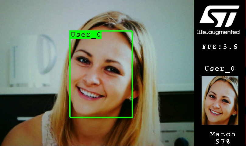
As soon as a face is detected within the camera captured frame, a rectangle box is drawn around it.
If the system is not able to match the detected face with one of the enrolled faces (either because the user face is not yet enrolled or because the Face Identification similarity score is lower than the default recognition threshold), the "No match" message is displayed on the right banner of the LCD screen and the rectangle box is drawn in red.
If the system is able to match the detected face with one of the enrolled faces, the rectangle box is drawn in green and a thumbnail (representing the user's enrolled face matching the detected face) is displayed on the right banner of the LCD screen along with the following information:
- The User Face ID
- The similarity score expressed in percentage (%).
When in nominal mode a FPS (Frame Per Second) information is displayed at the top of the right banner. This FPS corresponds to the number of frames that could be processed by the system in one second. As a result, the FPS is directly linked to the following timings:
- Duration of the Face Detection execution
- Duration of the Face Recognition execution
The camera frame acquisition is performed in parallel of the Face Detection and Face Recognition algorithm executions.
4.2. Enrollment mode
In order to enroll his face, the user must perform a long press on the blue joystick [SEL] button present on the board. There exist two options for triggering the enrollment:
- Either the enrollment is triggered immediately and automatically following up a long press on the joystick [SEL] button (= default behavior upon reset)
- Or the enrollment is triggered after a 3 seconds countdown following up a long press on the joystick [SEL] button (refer to section Configuration menu for details on how to enable this mode)
In both cases, once the enrollment is completed the "ENROLLMENT COMPLETED RELEASE JOYSTICK" message is displayed and a thumbnail corresponding to the enrolled face is displayed on the right banner of the LCD screen along with the User Face ID.
Up to 100 users can be enrolled in the system.
In this version of the application, the enrollment information is stored in volatile memory. As a consequence they are lost when resetting the system.
4.3. Camera orientation
By default the OV5640 camera sensor is configured in such a way that the original image is generated without being flipped or mirrored. The original image appears on the display without being flipped or mirrored when the relative position of the B-CAMS-OMV bundle versus the STM32H747I-DISCO board is as below:
If the relative position of the B-CAMS-OMV bundle versus the STM32H747I-DISCO board is different, there is the possibility to flip, mirror or flip & mirror the image captured by the OV5640 sensor. Refer to the section Configuration menu for details on how to modify the camera orientation settings.
4.4. Testing conditions
The user must keep in mind that the following parameters impact the accuracy of the recognition:
- Ambiance light and illumination
- Distance between the camera and the user (best results are achieved at distance <1.5 m)
- Enrollment phase: it is important to perform enrollment in good conditions (i.e. good illumination and without moving so to avoid blurring)
Adjusting the camera contrast by pressing the joystick [LEFT] and [RIGHT] buttons is a way to improve the accuracy of the recognition. For an optimized recognition, good illumination condition is important.
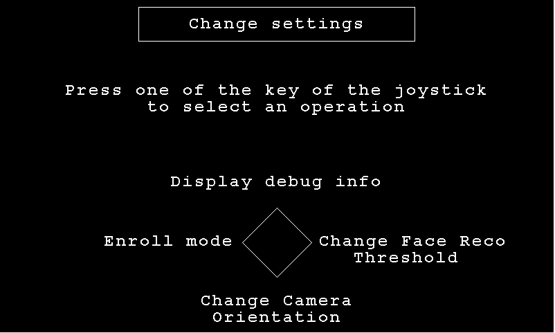
A configuration menu is available through a long press on the blue Wakeup button:
- "Display debug info" sub menu enables to visualize debug information such as:
- Execution timing
- Recognition threshold value
- Number of enrolled user
- "Enroll mode" sub menu enables to change the enrollment trigger mode:
- Countdown
- Immediate
- "Change Face Reco Threshold" sub menu enables to change the value of the recognition threshold:
- The recognition threshold corresponds to the similarity score above which the input face is successfully mapped to one of the enrolled faces.
- The default recognition threshold is set to 0.70 and its value can be updated by steps of 0.05.
- TAR (True Acceptance Rate) and FAR (False Acceptance Rate) are the metrics that have been used to compute the default value for the recognition threshold.
- The True Acceptance Rate represents the degree at which the system can correctly match the biometric information from the same person.
- The "False Acceptance Rate" is the probability of cases for which the system fallaciously authorizes an unauthorized person.
- A recognition threshold of 0.70 corresponds to a FAR of ~1% when plotting the TAR=f(FAR) graph using a dedicated (non-public) test database.
- "Change Camera Orientation" sub menu enables to change the flip and mirror settings of the camera :
- None: original captured image
- Flip: flips the captured image
- Mirror: mirrors the captured image
- Mirror and Flip: mirrors and flips the captured image
4.6. Programming the firmware binary in flash
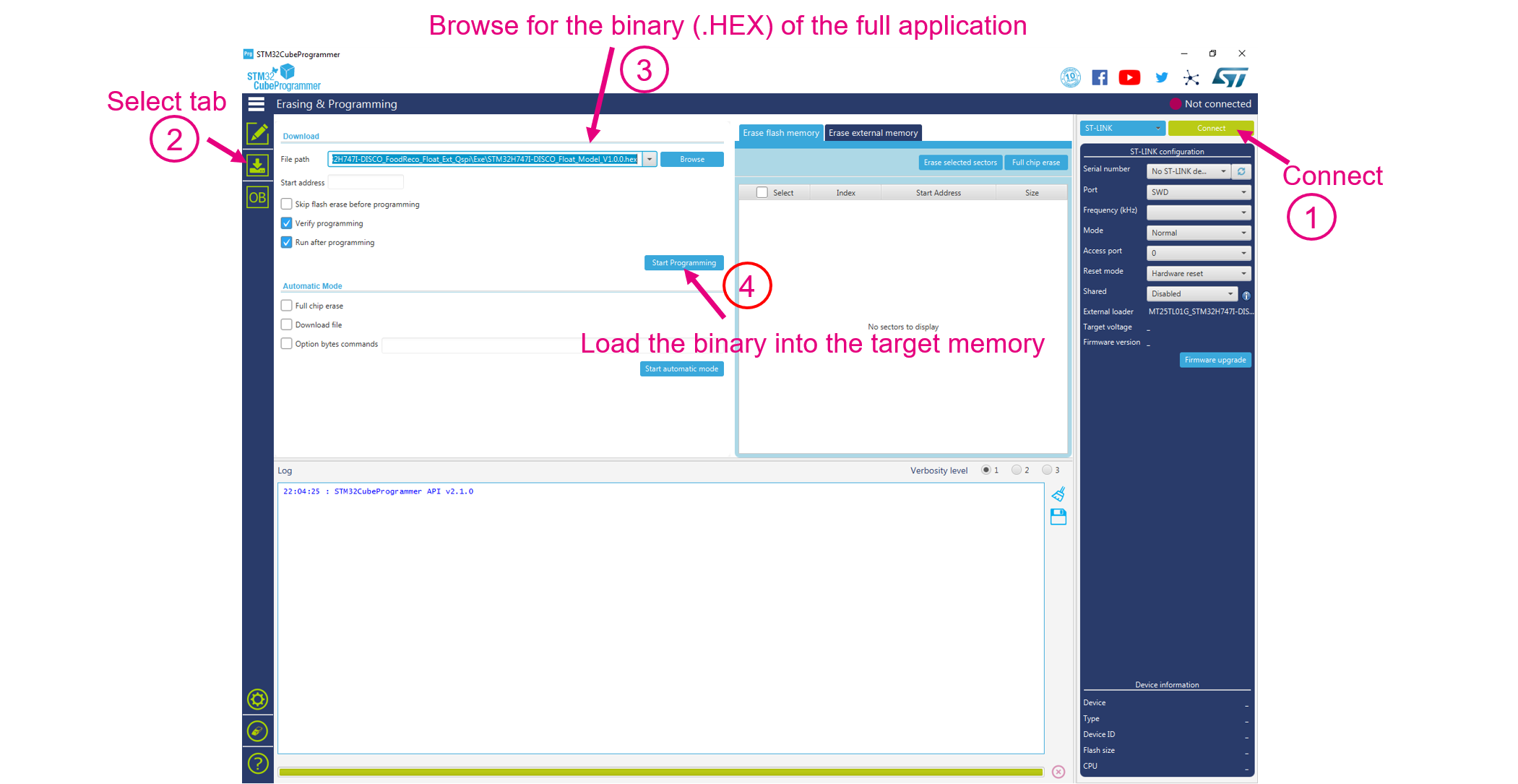
The STM32CubeProgrammer (STM32CubeProg) tool can be used to flash the binary into the target memory.
Here is below the procedure to follow:
- Connect to the target via ST-LINK
- Select the Erasing & programming tab on the left to access the Erasing & programming view shown in the picture below
- Browse for the binary of the application
- Program the target
