1. Technical description
This page describes the functioning of the BLE Mesh vendor model project and how to handle it.
A quick description of the BLE Mesh vendor model is available in the ST BLE-Mesh application note[1].
Further information on the vendor model is available in section 3 of this article.
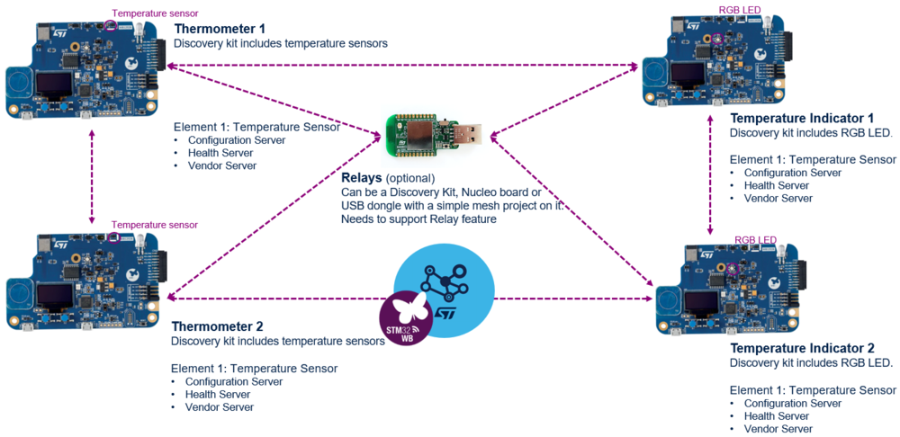
This project demonstrates the STM32WB application capabilities using BLE-Mesh solutions with a sensor module and by using specific vendor commands. This application aims to indicate the temperature measured by STM32WB5MM-DK Discovery kits using the RGB LED of other STM32WB5MM-DK Discovery kits.
To realize this project, four STM32WB5MM-DK Discovery kits[2] were used, including temperature, time of flight sensors, and RGB LEDs. In addition, USB dongles were added as relay nodes.
The temperature is sent periodically on the Mesh network by the STM32WB5MM-DK Discovery kit set in thermometer mode.
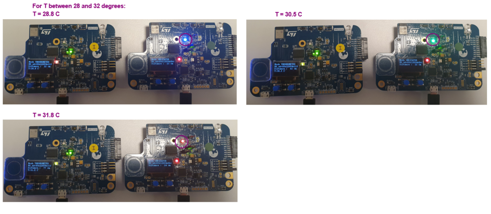
The RGB LEDs of the boards set in the indicator mode indicate the temperature variation with colors, blue for cold temperature, green for medium and red for high temperature.
Each STM32WB5MM-DK Discovery kit[2] (either thermometer and indicator mode) implements a vendor server model.
The thermometer can be placed far from the user, for example in different rooms, the temperature is measured and sent to the indicator nodes through BLE-Mesh vendor commands to update the LEDs status periodically.
2. Demonstration setup
2.1. Device requirement
Required material to set up the demonstration is as follows:
- Four STM32WB5MM-DK Discovery kits[2]: two as temperature sensing boards and two as LED indicator.
- One or more USB dongles[3]. (optional): as relay nodes.
- One smartphone with ST BLE Mesh application
2.2. Software setup
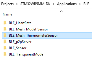
Thermometer application for STM32WB5MM-DK Discovery Kit[2] can be found on the latest STM32CubeWB MCU Package[4] :
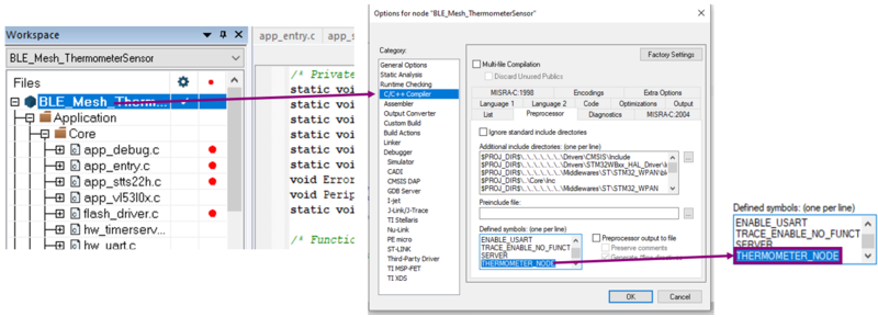
By default, this project is set up to build the thermometer node solution, in the project settings the THERMOMETER_NODE preprocessor definition is set.
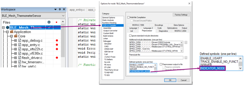
In order to build the LED Indicator Node solution, the user can replace the THERMOMETER_NODE definition by the INDICATOR_NODE:
Build the vendor project using one of these preprocessor definition to define if the node must be in the thermometer mode or in LED indicator mode.
3. Architecture
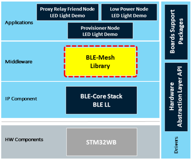
3.1. Firmware architecture
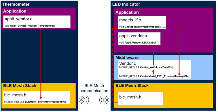
3.2. Vendor model code architecture
4. Vendor model code description
4.1. Set up your nodes and enable the vendor model
For both nodes, here thermometer and Indicator nodes. In mesh_cfg_usr.h file, setup your node:
- Number of element, you can define up to five elements per node:
/* Max elements: 5 */
#define APPLICATION_NUMBER_OF_ELEMENTS                                         1
- Number of models per element, you can define up to 11 models per element:
/* Max total Models per element = (SIG + Vendor) = 11 */
/* Max SIG Models per element */
#define USER_SIG_MODELS_MAX_COUNT                                              1
/* Max Vendor Models per element */
#define USER_VENDOR_MODELS_MAX_COUNT                                           1
- Enable models required for your demonstration, here vendor model server:
#define ENABLE_VENDOR_MODEL_SERVER (1)
This Number defines in which element the model is enable and works as a bitmap:
- Bit 0 corresponds to element 1
- Bit 1 corresponds to element 2
- Bit 2 corresponds to element 3
- …
For example #define ENABLE_VENDOR_MODEL_SERVER (5) means the model is enabled on element 1 and element 3 (as 5 = 0b0101).
4.2. Define your vendor command
To make the new vendor command work, some modifications must be done in Middleware, vendor.h file:
- The following lines define the vendor command categories:
/*******************Commands Received from Android/IoS*************************/
#define APPLI_TEST_CMD                  	0x1U
#define APPLI_DEVICE_INFO_CMD            	0x2U
#define APPLI_LED_CONTROL_STATUS_CMD      	0x3U
#define APPLI_ELEMENT_TYPE_CMD         		0x4U
#define APPLI_SENSOR_CNTRL_CMD             	0X5U
#define APPLI_DATA_CNTRL_CMD               	0xEU
//Add New Vendor Command here
/******************************************************************************/
If your new vendor command does not fit one of the defined categories, you can add your own category definition at this place.
- Add the new vendor sub command definition in one of the previous categories, for example, for the APPLI_LED_CONTROL_STATUS_CMD category:
/*****************Sub Commands for APPLI_LED_CONTROL_STATUS_CMD***************/
#define APPLI_CMD_ON                    	0x01U
#define APPLI_CMD_OFF                   	0x02U
#define APPLI_CMD_TOGGLE                	0x03U
#define APPLI_CMD_LED_BULB              	0x05U
#define APPLI_CMD_LED_INTENSITY          	0X06U
#define APPLI_CMD_LED_THERMOMETER    		0X07U
//Add New LED Control Vendor Sub Command here
/******************************************************************************/
4.3. Publish a vendor command
In the demonstration case, the thermometer node must publish the vendor command to the indicator node, below is the code of the function sending the APPLI_LED_CONTROL_STATUS_CMD and APPLI_CMD_LED_THERMOMETER commands:
/**
* @brief  Publish Temperature Command for Vendor Model
* @param  srcAddress: Source Address of Node
* @param  temperature: Temperature Measured
* @retval void
*/
void Appli_Vendor_Publish_Temperature(MOBLE_ADDRESS srcAddress, MOBLEUINT8 temperature)
{
  	MOBLE_RESULT result = MOBLE_RESULT_SUCCESS;
  	MOBLEUINT8 AppliBuff[2];
  	/* changes the LED status on other nodes in the network */

 	 AppliBuff[0] = APPLI_CMD_LED_THERMOMETER;
  	AppliBuff[1] = temperature;
  	result = BLEMesh_SetRemotePublication(VENDORMODEL_STMICRO_ID1, srcAddress,
                                            			APPLI_LED_CONTROL_STATUS_CMD,
                                            			AppliBuff, sizeof(AppliBuff),
                                            			MOBLE_FALSE, MOBLE_TRUE);
  	if(result)
  	{
    		TRACE_I(TF_VENDOR_M, "Publication Error \r\n");
  	}
}
In the demonstration, the previous function is called in the application background task, if the temperature gap between the value recorded and the last value displayed is greater than a minimal value. For further project, you can define your own publication functions, and call them on different events, such as, button pressing, specific sensor measurements, interruption.
4.4. Receive and manage a vendor command
4.4.1. The new vendor command is included in an existing group
This is the case in the thermometer demonstration, the APPLI_CMD_LED_THERMOMETER sub command is managed as a LED Control command (APPLI_LED_CONTROL_STATUS_CMD).
In this case, the temperature indicator node must receive and manage the vendor command sent by the thermometer node. To perform that, identify the function processing the specific group of commands, here Appli_Vendor_LEDControl function. And, in the switch on the sub command identifiers, add a case corresponding to the new command defined:
MOBLE_RESULT Appli_Vendor_LEDControl( MOBLEUINT8 const *data, MOBLEUINT32 length,
                                      		 MOBLEUINT8 elementIndex , MOBLE_ADDRESS dst_peer)
{
	[…]
	switch(subCommand)
 	{
		[…]
		 /* Thermometer command */
#ifdef APPLI_CMD_LED_THERMOMETER
  		case APPLI_CMD_LED_THERMOMETER:
   		 {
  			 [ ACTION TO PERFORM ]
  			 break;
    		}
#endif
		[…]
 		}
}
4.4.2. The new vendor command is included in a new group
In this case, you must:
- Add your command into the Vendor_Opcodes_Table[], in vendor.c.
- Define the function processing the new group of commands, in appli_vendor.c/.h.
- Define the callback for this function into the Appli_Vendor_cb_t definition, in vendor.h.
- Associate the function to the corresponding callback into the VendorAppli_cb definition, in models_if.c.
- Call the callback into Vendor_WriteLocalDataCb or Vendor_ReadLocalDataCb, in vendor.c.
5. Demonstration handling
1. Flash your boards with the different node projects.
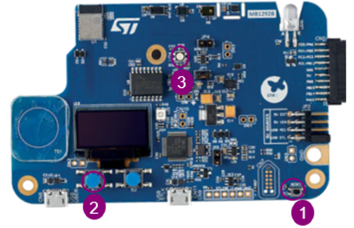
Ensure your boards are un-provisioned by pressing RESET ![]() and SW1
and SW1 ![]() buttons simultaneously, release RESET and keep SW1 pressed until the LED1
buttons simultaneously, release RESET and keep SW1 pressed until the LED1 ![]() blinks:
blinks:
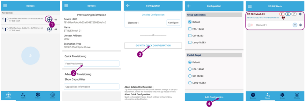
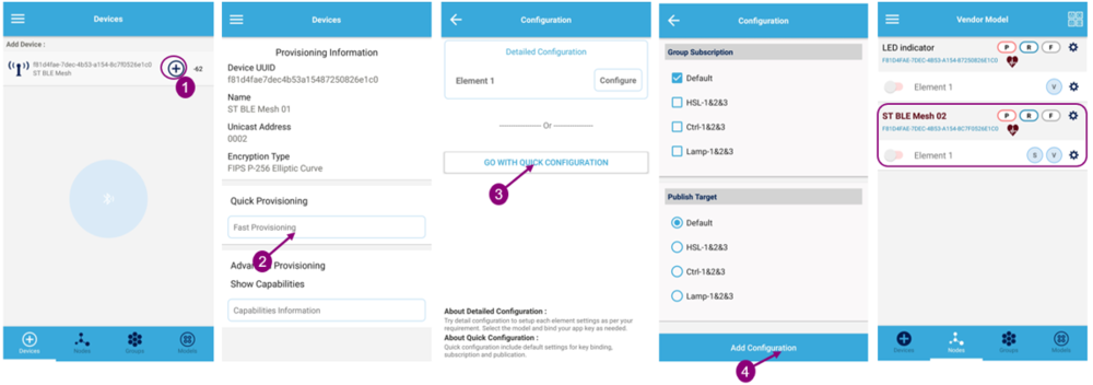
2. Launch the smartphone application and provision the different nodes.
LED indicator node:
Thermometer node:
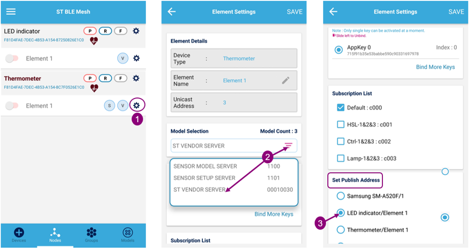
3. Rename the different nodes.
4. Set the publication address for the thermometer nodes.
5. Reproduce these steps for all thermometer / LED indicator nodes.
the result is the following publication address schematic:
With the previous steps followed, the LED indicator boards must reflect the temperature for their corresponding thermometer board.
6. References

