1. Presentation
This page describes how to quickly handle Bluetooth® LE-MeshLightingPRFNode' example.
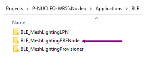
This project can be found on the latest STM32CubeWB MCU Package[1], and generates a basic node supporting Proxy-Relay-Friend features.
It is a good introduction to handle and have a first approach of ST Bluetooth® LE-mesh solution.
Some information provided below can be retrieved in the STM32WB Bluetooth® LE-mesh hands-on[2] video .
2. Functioning
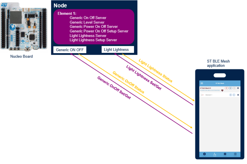
Bluetooth® LE-MeshLightingPRFNode project demonstrates STM32WB application capabilities using the ST Bluetooth® LE-mesh with basic models.
3. Getting started
Bluetooth® LE-MeshLightingPRFNode project implements a Bluetooth® LE-mesh node supporting proxy, relay and friend features. These features are sufficient to set up a first mesh network, see Bluetooth® LE mesh wiki page.
3.1. Requirements
Software and system requirements
The software required are the following (minimum IDEs version):
- IAR Embedded Workbench for ARM (EWARM) toolchain V8.20.2
- RealView Microcontroller development Kit (MDK-ARM) toolchain V5.23
- STM32CubeIDE toolchain V1.7.0 [3].
Programmer:
- STM32CubeProgrammer[4]: to flash the board with an already generated binary
Smartphone application:
- ST BLE Mesh application
More information about software and system requirements are available in the ST Bluetooth® LE-mesh application note[5].
Hardware requirements
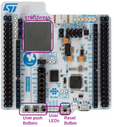
P-NUCLEO-WB55[6] is required to set up the demonstration.
More details about the board and other hardwares required are available in the application note[5], or in the online ST Bluetooth® LE-Mesh MOOC[7].
3.2. Build and install the application
Details about the application build and installation are given into the Application Note[5].
However, some more details about the build process using STM32CubeIDE[8] are available below.
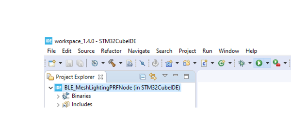
Launch the Cube IDE[8] .project of the demonstration, ensure that your project is correctly visible into the project explorer view.
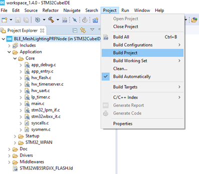
Build you project by reproducing the following steps:
Flash it on the board (only for Nucleo board):
3.3. Install the application from CubeProgrammer
It is also possible to flash the previously built binary using the STM32CubeProgrammer software[9].
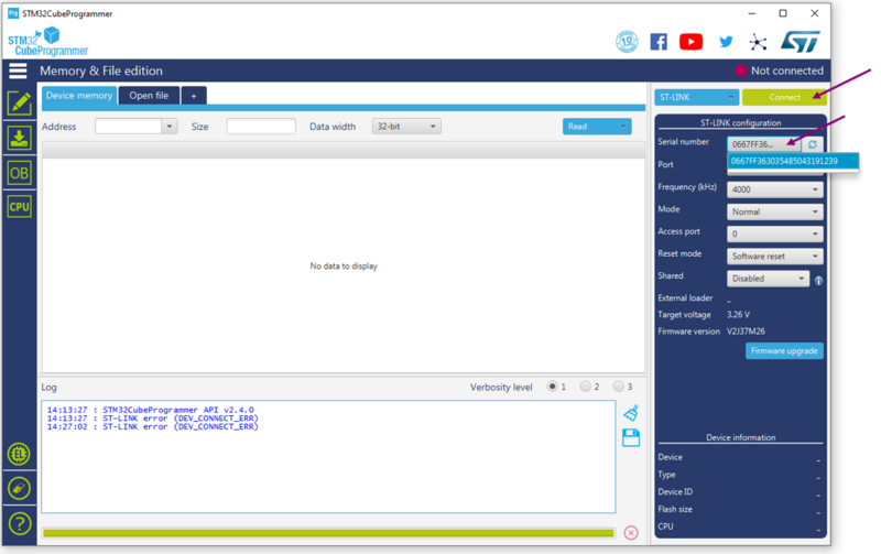
Select your device and connect:
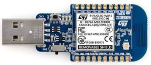
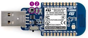
- For USB dongle, move the SW2 switch on Boot0 before, then connect it to the computer and use the USB mode
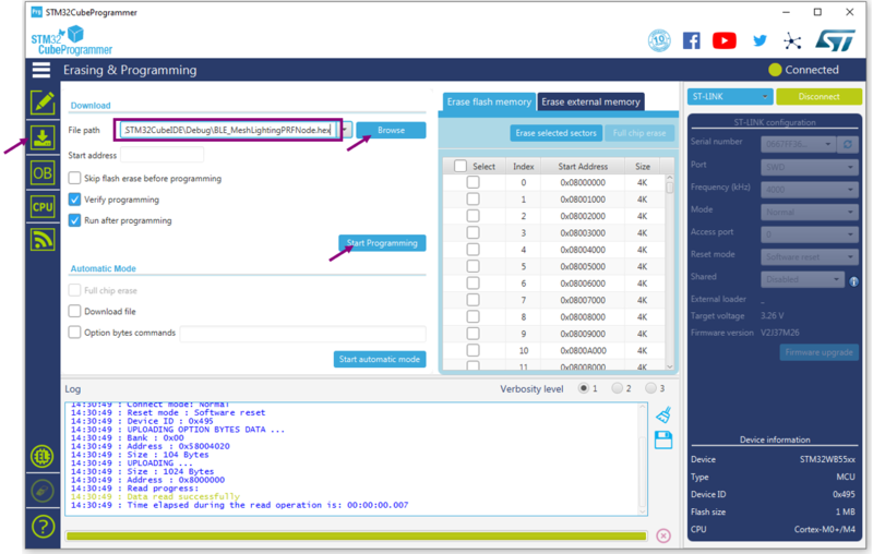
Once connected, the device information is displayed on the CubeProgrammer interface. Click on the programming icon, in the left column. Select the project binary to flash (namely, BLE_MeshLightingPRFNode.hex). Then, click ok the Start Programming button:
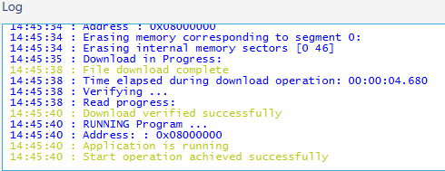
When the programming is complete the following logs are displayed:
3.4. UART interface
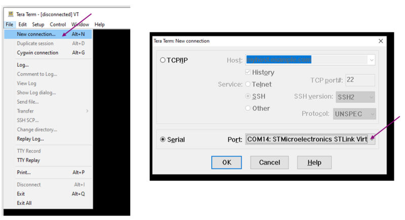
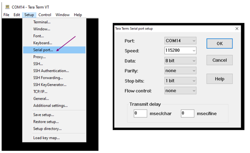
The board is connected to a PC via a USB connection. Use any convenient terminal software to open the serial communication port of the PC to check messages from the board. Select your serial port and set up your connection. The figure below shows the steps to follow (example done with Tera Term software).
Set a new serial connection to the ST platform:
Set up your serial connection as shown below:
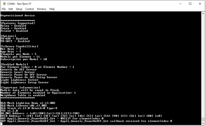
Once the board is connected and the terminal window setup, press the reset button of the board. The following messages are printed to the virtual COM window when the firmware starts successfully.
3.5. Application handling
A full description of ST BLE Mesh smartphone application can be found in the Android application user manual[10], and the iOS application user manual[11].
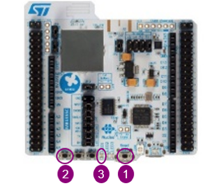
Ensure the board is un-provisioned:
- For Nucleo board, press RESET
 and SW1
  buttons simultaneously, release RESET and keep SW1 pressed until the LED1
  blinks:
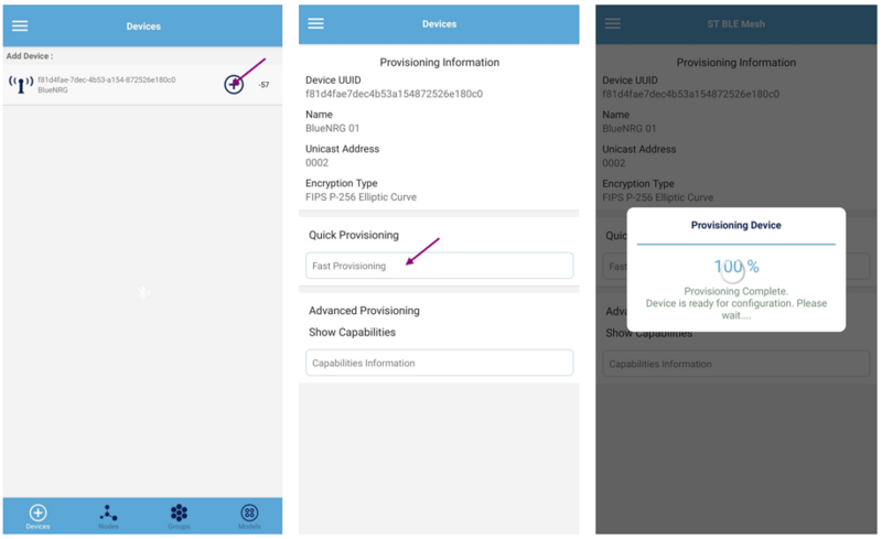
Launch the ST Bluetooth® LE mesh smartphone application,. The illustrations below are based on the Android version of the application.
Provision the device:
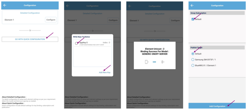
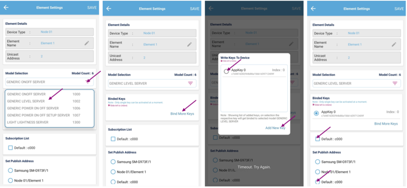
Configure the device using the quick configuration button, select the App Key and set the publication and subscription addresses:
The node is now provisioned. You can click on the first settings button to rename the node. The second button to access the elements and models setup. This allows to change the subscription and publication addresses for each model.
If an issue occurs during provisioning, for example the App Key binding failed for one or more models, you can bind the App Key from this interface, and change the publication/subscription addresses.
From the node interface, you can send a Generic OnOff command to pilot the board LED ![]() .
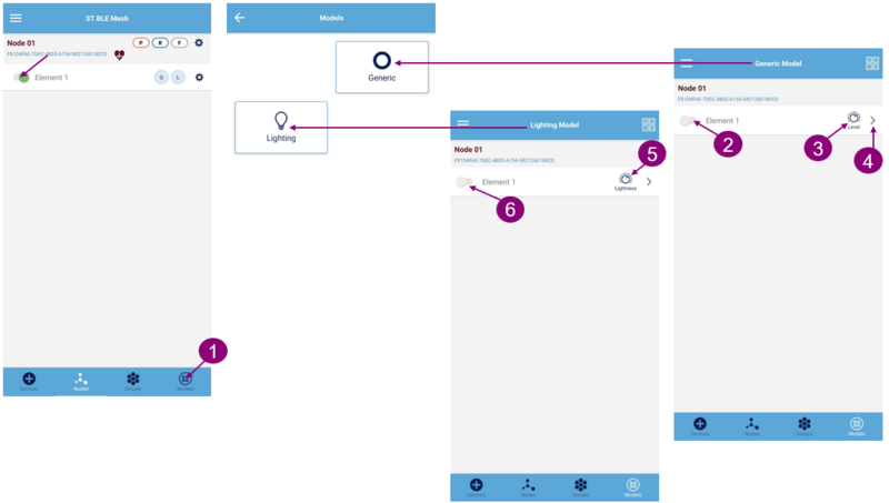
You can also switch to the model interface, where you can select the model available on the nodes of your network.
Generic model interface allows playing with the Generic OnOff
.
You can also switch to the model interface, where you can select the model available on the nodes of your network.
Generic model interface allows playing with the Generic OnOff ![]() , Generic Level
, Generic Level ![]() and Generic Power OnOff
and Generic Power OnOff ![]() commands.
Lighting Model interface allows to play with the Light Lightness Commands
commands.
Lighting Model interface allows to play with the Light Lightness Commands ![]() and
and ![]() .
.
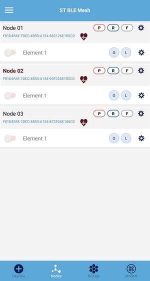
You can add several nodes to your network by repeating the provisioning process on other boards.
4. References
- ↑ STM32CubeWB MCU Package
- ↑ Jump up to: 2.0 2.1 STM32WB Bluetooth® LEMESH hands-on
- ↑ STM32CubeIDE
- ↑ STM32CubeProgrammer software
- ↑ Jump up to: 5.0 5.1 5.2 AN5292 - How to build Bluetooth® Low Energy mesh application for STM32WBx5 line microcontrollers
- ↑ P-NUCLEO-WB55 Pack
- ↑ STM32WB Networking – Bluetooth® LE MESH MOOC
- ↑ Jump up to: 8.0 8.1 STM32CubeIDE software
- ↑ STM32CubeProgrammer
- ↑ UM2180 - Getting started with the ST Bluetooth® LE-Mesh Android application
- ↑ UM2361 - Getting started with the ST Bluetooth® LE-Mesh iOS application
