FP-AI-NANOEDG1 is a condition monitoring function pack based on vibration sensor data. It is based on STM32Cube ecosystem and is designed for STM32 series of microcontrollers.
This article provides an overview on the following topics:
- Overview of the required hardware and software,
- Setting up the hardware and software components,
- Performing the vibration sensor data collection using the provided function pack,
- Generating, Installing and testing the NanoEdge™ AI machine learning libraries on the sensor node STM32L562E-DK using the provided function pack, and
- Some links to useful online resources, which can help a user to better understand the project and then customize the project for his own needs.
1. Hardware and software overview
1.1. Discovery kit with STM32L562QE MCU hardware description
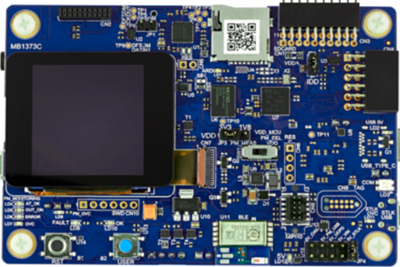
The STM32L562E-DK is a complete demonstration and development platform, for Arm® Cortex®-M33 with Arm® TrustZone® and ARMv8-M mainline security extension core-based STM32L562QEI6QU microcontroller. The onboard MCU can run at 110 MHz/165 DMIPS, and has 512 Kbytes of Flash memory and 256 Kbytes of SRAM. The other key specifications of the board are:
- 1.54" 240 × 240 pixel-262K color TFT LCD module with parallel interface and touch-control pane, which can be used for standalone demos,
- iNEMO 3D accelerometer and 3D gyroscope,
- MEMS digital microphones, and a low-power stereo audio CODEC with headphone amplifier,
- 2 user LEDs,
- User and reset push-buttons,
- 512-Mbit Octal-SPI Flash memory.
- In terms of board connectors it includes :
- USB Type-C®,
- Bluetooth® V4.1 Low Energy module,
- microSD™ card,
- Stereo headset jack including analog microphone input, and
- JTAG debugger.
For further details readers can have a look at the data brief for STM32L562E-DK.
1.2. FP-AI-NANOEDG1 software description
The FP-AI-NANOEDG1 is a function pack with basic project to easily jump-start the condition monitoring applications using vibration sensor data. The project is based on the STM32Cube ecosystem and serves as a host, for the AI libraries generated from NanoEdge™ AI Studio, a solution from Cartesiam. The following figure shows the software architecture of the FP-AI-NANOEDG1.
The key features of the software are:
- Complete firmware to enable a sensor node for data logging, condition monitoring and predictive maintenance applications based on vibration data,
- AI utility for parsing and conditioning the data logged on a microSD™ card through CLI,
- A free license with user-friendly terms.
- Simple LCD user interface, and
- Autonomous mode controlled by user button.
- It also provides a wired interactive command-line interface (CLI) for :
- Node and sensor configurations,
- For high-speed data logging using on board accelerometer, and
- Management of the learning and detection phases of Cartesiam Machine Learning solution.
2. Project setup with example application
2.1. HW prerequisites and setup
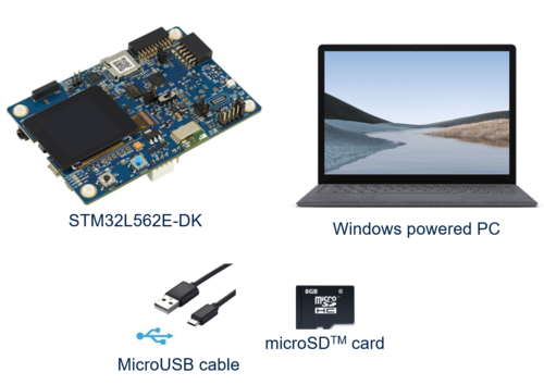
To use the FP-AI-NANOEDG1 function pack on STM32L562E-DK, following hardware items are required:
- STM32L562E-DK development kit board,
- Windows® powered laptop/PC (Windows® 7, 8, or 10),
- A USB cable to connect the PC to the Micro-B USB connector (CN17) on the board,
- A microSD™ card for data logging,
2.2. Software requirements
2.2.1. FP-AI-NANOEDG1
- Download the FP-AI-NANOEDG1 package from ST website, extract and copy the .zip file contents into a folder on your PC. The package contains binaries and source code with project files for STM32CubeIDE, for sensor board STM32L562E-DK.
2.2.2. STM32CubeIDE
- STMCubeIDE is an Integrated Development Environment (IDE) for STM32 microcontrollers and microprocessors.
- Users need to download the software from STM32CubeIDE, and install it.
2.2.3. STM32 ST-LINK Utility
- A software interface for programming STM32 microcontrollers. This software is only required to install the prepared binaries provided in the function pack folder at start. Note that this software will be used by not just users to install the already provided binaries but by STM32CubeIDE also to program the boards with the generated binaries.
- This software can be downloaded from STSW-LINK004.
2.2.4. Tera Term
- Tera Term is an open source and freely available software terminal emulator, which is used to host the CLI of the FP-AI-NANOEDG1 through serial connection.
- Users can download and install the latest version available from Tera Term.
2.2.5. NanoEdge AI Studio
The function pack is to be powered by Cartesiam. For this, the user needs to generate the libraries from the NanoEdge AI Studio and then embed these libraries in the FP-AI-NANOEDG1. The Studio can be downloaded from this link. Cartesiam provides a free evaluation version for the STM32L562E-DK board.
2.3. FP-AI-NANOEDG1 console application
FP-AI-NANOEDG1 provides an interactive command-line interface (CLI) application. This CLI application provides a user the ability to configure and control the sensor node, to log the data to generate the Cartesiam NanoEdge AI libraries and then perform the condition monitoring by training and testing these libraries on the edge. Following sections provide a small guide on how a user can install this CLI application on sensor board and control it through the CLI on a PC.
2.3.1. Get the function pack
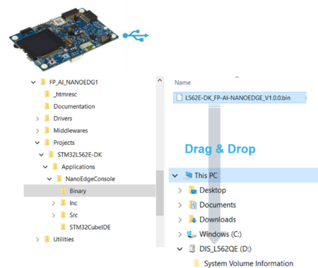
The first step is to get the function pack. The FP-AI-NANOEDG1 can be downloaded from ST website. Once the pack is downloaded, the user can unpack/unzip it and copy the contents to a folder on the PC. The steps of the process along with the contents of the folder are shown in the following image.
2.3.2. Installing the CLI application on the sensor board STM32L562E-DK
Once the package has been downloaded and unpacked, the next step is to program the sensor node with the binary of the function pack. For the convenience of the users, the function pack is equipped with a pre-built binary file of the project. The sensor board can be very easily programmed with the provided binary by simply performing a drag-and-drop action as shown in the figure below.
Note : This process assumes the board is in its form right from out of the box. If the board has been used for some other projects and some jumpers and switch configurations have been changed, they need to be set back to the default settings as provided in the table below.
| Jumpers | |
|---|---|
| JP1 | Open |
| JP2 | Close |
| JP3 | (1-2 closed) 3V3 |
| JP4 | (1-2) 5V_STLK |
| JP5 | Close |
| JP6 | Open |
| JP7 | Open |
| Switches | |
| SW1 | VDD |
| SW2 | Left APPLI Mode |
2.3.3. Use the command line interface (CLI)
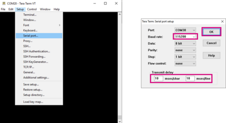
Once the sensor board is programmed with the binary of the project, the next step is to set up the serial connection of the board with the PC through Tera Term. The first step is to create a new connection. This can be done either by navigating from the toll bar of Tera Term or by entering the key combination Alt + N . This will show a dialog as shown in the figure below. Select the port on which your sensor board is attached. In the following example, communication port 28 is selected with title COM28: STMicroelectronics - STLink Virtual COM Port.
The next step is to configure the connection. Following image shows the configurations to be chosen for the serial connection to have an effective communication between computer and sensor board.
Once the connection is made the user will see a message
Console command server.
Type 'help' to view a list of registered commands.
$
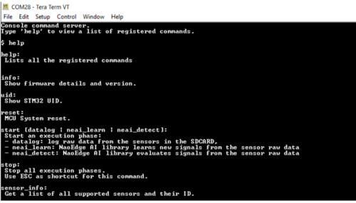
Typing help will show the list of all available commands as presented in the table below.
| Command | String | Description |
|---|---|---|
| CS1 - Generic commands | ||
| help | help | Lists all registered commands with brief usage guidelines. Including the list of applicable parameters. |
| info | info | Shows firmware details and version. |
| uid | uid | Shows STM32 UID. |
| date_set | date_set <date&time> | Sets date and time of the MCU system. |
| date_get | date_get | Gets date and time of the MCU system. |
| reset | reset | Resets the MCU system. |
| start | start <"datalog", "neai_learn", or "neai_detect" > | Starts an execution phase according to its execution context, i.e. datalog, neai_learn or neai_detect. |
| stop | stop | Stops all running execution phases. |
| CS2 - PdM specific commands | ||
| neai_init | neai_init | (Re)initializes the AI model by forgetting any learning. Used in the beginning and / or to create a new NanoEdge AI model. |
| neai_set | neai_set <param> <val> | Sets a PdM specific parameters in an execution context. |
| neai_get | neai_get <param> | Displays the value of the parameters in the execution context. |
| CS3 - Sensor configuration commands | ||
| sensor_set | sensor_set <sensorID>.<subsensorID> <param> <val> | Sets the ‘value’ of a ‘parameter’ for a sensor with sensor ID provided in ‘id’. |
| sensor_get | sensor_get <sensorID>.<subsensorID> <param> | Gets the ‘value’ of a ‘parameter’ for a sensor with sensor ID provided in ‘id’. |
| sensor_info | sensor_info | Lists the type and ID of all supported sensors. |
3. Data collection
Once the user has verified that the binary has been programmed and the serial connection is already setup to the sensor node, user can start the data logging. The following section provides the guide for performing the data log.
3.1. Configure the sensor for data logging
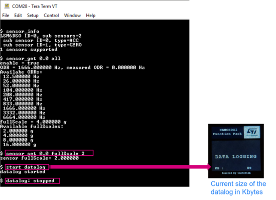
The FP-AI-NANOEDG1 provides the capability of logging the inertial data through onboard accelerometer LSM6DSO in STM32L562E-DK, through the CLI application. The CLI interface provides the user with a capability to not just log the data with the default configurations of the sensor but also equip the user with the capability to configure the sensor by setting different values to the different variables. The configurable options for LSM6DSO include:
- Activate/deactivate the sensor or a sub-sensor,
- Set an output data rate (ODR) from the list of available options,
- Set full scale range from the list of available options.
Furthermore, the list of all the available sensors and sub-sensors can be displayed on the CLI console by entering the command:
$ sensor_info
This command will show the supported sensors with their sensor and sub-sensor IDs. The detailed information of a given supported sensor or sub-sensor can be shown by typing command:
$ sensor_get <sensor_id.sub-sensor_Id> all
Similarly, the values for any of the available configurable parameters can be set through command
$ sensor_set <sensor_id.sub-sensor_Id> <param> <val>
3.2. Logging the data
Once the sensor is configured to the wished configuration values, the data logging can be started by simply entering the command
$ start datalog
in the CLI console. While the data logging is under progress, the LCD screen on the sensor board shows the active size of the data log in kilobytes as shown in the figure above. Once the data is logged for the required time, the process can be stopped by either pressing the Esc button, or by typing the command
$ stop
in the CLI console.
With every successful data logging command, a new data folder will be created in the SD card with the name format STM32_DL_XXX, with DeviceConfig.json and LSM6DSO files. These files contain the sensor configuration at the time of start datalog command issued, and the sensor data respectively.
4. Condition monitoring using NanoEdge AI Machine Learning library
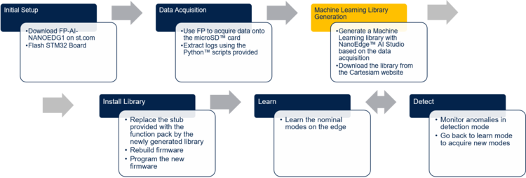
This section provides complete method to set up an application for condition monitoring using FP-AI-NANOEDG1. The steps are provided with brief details in the diagram below.
The details on how to set up the sensor board with function pack as well as data collection have been already provided in the sections above. Following sections provide the details on library generation, installation, training and testing.
4.1. Generating a condition monitoring library
The AI libraries for the condition monitoring for this function pack are generated and provided by NanoEdge AI Studio, a solution provided by Cartesiam. This section provides step-by-step guide on how to generate these condition monitoring libraries, installing them on the sensor node by linking them to the provided project in FP-AI-NANOEDG1 and then using them to perform the condition monitoring on the edge, by running first in training and then detection mode.
4.1.1. Data logging for normal and abnormal conditions
The library generation requires some sample data to be provided to the NanoEdge AI Studio. This data will provide the context of the set up to be monitored. The first step is to log the data for the normal and abnormal conditions using the data logging application provided in this function pack. Note that this data is to generate the libraries, so the users are advised to record data by exposing all the possible normal and any known abnormal conditions.
4.1.2. Data preparation for library generation with NanoEdge AI Studio
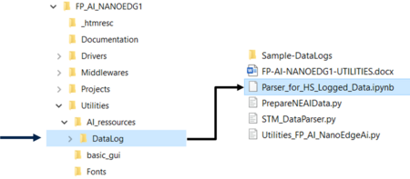
The data logged through the datalogger is in the binary format and is not user readable in its current condition. In order to convert this data to useful form, FP-AI-NANOEDG1 provides Python™ utility scripts. These scripts along with example usage can be found in a Parser_for_HS_Logged_Data.ipynb , a Python™ Jupyter™ Notebok, located on the path FP-AI-NANOEDG1/Utilities/AI-resources/DataLog/ as shown in the figure below.
4.1.3. Library generation using NanoEdge AI Studio
The process of generating the libraries with Cartesiam NanoEdge AI studio consists of five steps.
- Hardware description
- Choosing a microcontroller type : Arm® Cortex®-M33
- Maximum amount of RAM to be allocated for the library: Usually a few Kbytes will suffice (but it depends on the data frame length used in the process of data preparation).
- Sensor type : 3-axis accelerometer
- Providing the sample contextual data to adjust and gauge the performance of the chosen model. This step will require data for:
- Nominal or normal case
- Abnormal case
- Benchmarking of available models and choose the one that complies with the requirements.
- Validating the model for learning and testing through the provided emulator which emulates the behavior of the library on the edge.
- The final step is to compile and download the libraries. In this process, the flag
"-mfloat-abi"has to becheckedfor using libraries with hardware FPU.
Detailed documentation on the NanoEdge AI Studio.
4.2. Installing the NanoEdgeAI Machine Learning library
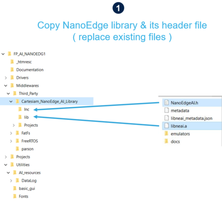
Once the libraries are generated and downloaded from Cartesiam NanoEdge AI Studio, the next step is to incorporate these libraries to FP-AI-NANOEDG1. The FP-AI-NANOEDG1, comes with the library stubs in the place of the actual libraries generated by NanoEdge AI Studio. This is done to make it easy for users to link the generated libraries and have a place holder for the libraries, which are generated through following the steps provided in the previous section. In order to link the actual libraries, the user needs to copy the generated libraries and replace the existing stub/dummy libraries and header files NanoEdgeAI.h, and libneai.a files present in the folders Inc, and lib, respectively. The relative paths of these folders are /FP_AI_NANOEDG1/Middlewares/Third_Party/Cartesiam_NanoEdge_AI_Library/ as shown in the figure below.
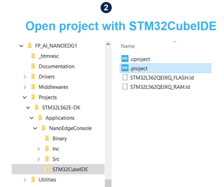
Once these files copied, the project must be reconstructed and programmed on the sensor board in order to link the libraries. For this, user needs to open the .project file from the FP-AI-NANOEDG1 folder, located at the path FP_AI_NANOEDG1/Projects/STM32L562E-DK/Applications/NanoEdgeConcole/STM32CubeIDE/ as shown in the step 2 in figure below.
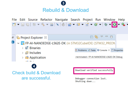
To install the new firmware after linking the library, connect the sensor board and rebuild the project using the play button. See the console for the outputs and wait for the Build and Download success message as shown in step 4 in the figure below.
4.3. Testing the NanoEdgeAI Machine Learning library
Once the Downoad verified successfully message appears, the generated AI libraries are linked to the firmware on the sensor board and are ready to test.
Note that in their current form, the libraries have zero knowledge of the normal and abnormal conditions, and to perform the condition monitoring effectively, it is important to learn the normal behavior of the setup/machine to be modeled. This can be done by starting the learning process. The learning phase can be started by issuing start neai_learn command in console. Starting this command will show the process of learning and will show a message on the console every time learning is performed on a new signal, as shown in below code snippet.
$ start neai_learn
NanoEdgeAI: starting
$ 1 signal learning: SUCCESS.
2 signal learning: SUCCESS.
3 signal learning: SUCCESS.
4 signal learning: SUCCESS.
5 signal learning: SUCCESS.
6 signal learning: SUCCESS.
The process can be stopped either by issuing the
$ stop
command or by simply pressing the ESC key on the keyboard.
The alternate way to start the learning process is to long press the user button, as shown in the splash screen of the sensor node. This button can be used to start the learning in standalone as well as in computer-operated mode. The process can be stopped by simply pressing the user button again.
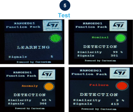
Once the normal conditions are learnt, the user can start the condition monitoring process by starting the neai_detect mode. This mode can be started by issuing the command
$ start neai_detect
NanoEdgeAI: starting
or by short pressing the user button on the sensor board. The LCD will show the detection mode is activated along with the status through the LED in the screen, Green for Normal, Orange for Anomaly, and Red for Failure, as shown in the screen shots in figure above.
4.3.1. Some hyper-parameters in condition monitoring
For the convenience of the users CLI also provides some handy options to run the inference and learning process of the condition monitoring easily. Users can see all the variables they can play with by issuing following command:
$ neai_get all
NanoEdgeAI: signals = 0
NanoEdgeAI: sensitivity = 1.000000
NanoEdgeAI: threshold = 95
NanoEdgeAI: timer = 0
Each of the these parameters can be configured using neai_set <param> <val> command. The details are provided in the command table above.
This section provides small details on neai_set signals <nr of signals> . Using this command, a user can start the learning or condition monitoring mode for a given number of samples. For example, to learn on 100 signals, the user can issue this command, before issuing the learn command. In the following snippet an example is presented where the learning is performed for 10 signals.
$ neai_set signals 10
NanoEdgeAI: signals set to 10
$ start neai_learn
NanoEdgeAI: starting

$ 1 signal learning: SUCCESS.
2 signal learning: SUCCESS.
3 signal learning: SUCCESS.
4 signal learning: SUCCESS.
5 signal learning: SUCCESS.
6 signal learning: SUCCESS.
7 signal learning: SUCCESS.
8 signal learning: SUCCESS.
9 signal learning: SUCCESS.
10 signal learning: SUCCESS.
NanoEdge AI: stopped
The threshold parameter is used to report the anomalies. For any signal which has similarities below the threshold value is reported as anomaly. The default value used in the CLI application is 95. Users can change this value by using neai_set threshold <val> command.
The sensitivity parameter is used as an emphasis parameter. The default value is set to 1. Increasing this sensitivity will mean that the matching of the signals is to be performed more strictly, reducing it will also reduce the matching calculation process, i.e. resulting in higher matching values.
For details, users are invited to read the detailed documentation of NanoEdge AI studio.
