1. LC3 codec
The LC3 codec is an algorithm allowing to compress audio data for transmitting over the air.
This codec must be supported by any application build over the generic audio framework and Bluetooth® Low Energy 5.2 isochronous feature. It runs the channel independently, has a complexity similar to opus, and can be used for either voice and music with a better quality.
1.1. LC3 generalities
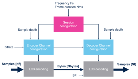
An LC3 session is defined by:
- The sampling frequency Fs: 8, 16, 24, 32, 44.1, or 48 kHz
- The frame duration Nms: 7.5 or 10 ms
The frame duration varies a little with 44.1 kHz, refers to LC3 specification [1] for details
Then each channel is referring to a session with additional information:
- The mode: encoding or decoding
- The PCM (pulse code modulation) sample width: 16, 24, or 32 bits
- The bitrate within a list of recommended bitrates
The LC3 supports bitrate updates, but Bluetooth® Low Energy profiles do not use this feature
Also, the LC3 codec embeds a packet loss concealment algorithm. This algorithm ensures signal continuity and reduced glitches in cases of corrupted/missing packet. It is triggered by either an external indicator BFI or an internal frame analysis.
At the encoder side, the data flow is:
- Data input
- A PCM signal buffered into an Nf samples per channel, this size is linked to the frame duration and frequency.
- For example, a 10 ms frame at 32kHz leads to 320 samples
- Data output
- An encoded buffer per frame per channel of size Nbytes, this size is directly linked to the bitrate and is within the range of 20 to 400 bytes.
- In our example, 64 kbps leads to 80 bytes, so a compression factor of 8 for 16 bits per sample
1.2. LC3 implementation
Our LC3 embeds a PLC algorithm based on the annex B of the LC3 specification and the implementation is based of floating-point numbers.
Thus, the provided library is compiled for Cortex®-M33 with FPU and DSP instructions and is optimized for speed.
Provided by the upper layer, the following RAM must be allocated for running the full feature LC3:
- 604 bytes per session
- 4820 bytes per encoding channel
- 8340 bytes per decoding channel
Also, at least 7000 bytes are allocated by the encoder over the stack, or 4700 bytes if the only decoder is used.
The flash footprint of the full codec represents around 120 Kbytes and can be reduced at the linking time if only one mode is used.
Here is an overview of the CPU load measured on a CPU running at 100 MHz from flash with instruction cache enabled.
This LC3 implementation is certified with the QDID 237184.
2. Audio path architecture
2.1. Overview
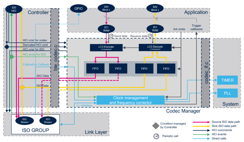
The Bluetooth specification allows various paths for isochronous data. While the legacy path uses the HCI interface, a vendor-specific data path allows a better handling of processes and latencies. This architecture allows putting the audio codec bellow the HCI interface and it can be configured using standard HCI commands.
ISO data exchanged with the link layer are called 'Media packets'. These packets can be either an encoded frame or a raw frame (transparent mode). They can also be several channels multiplexed and/or several blocks concatenated. This format is defined in LTV structures and is given through HCI commands.
2.2. Clock synchronization
2.2.1. Generalities
The Bluetooth specification says when using unframed PDU, the upper layer must synchronize the generation of its data to the effective transport timings. In Bluetooth® Low Energy, transport timings are defined by the link layer controller's sleep clock, and upper layers (including audio peripheral) at both receiver and controller side have to synchronize to that clock. This statement is also applicable when using framed PDU to prevent the generation of glitches and to maintain a consistent data rate from the audio source to the audio sink.
The most constraining role is Bluetooth® Low Energy receiver, meaning the device has to synchronize it is audio peripheral clock to the remote link layer.
Being a Bluetooth® Low Energy controller brings less constraints since we only need to synchronize to a local clock. If power consumption is not a deal, the sleep clock could be directly taken from the active clock.
However, being a receiver on the audio peripheral brings a constraint impossible to respect.
Note that it is not recommended to run Bluetooth® Low Energy audio based on a non-accurate sleep clock like LSI.
| RF role | Audio role | Sleep clock source | Synchronization |
|---|---|---|---|
| Master | Master | LSE | Local synchronization or through link layer |
| LSI | Local synchronization or through link layer (not recommended) | ||
| HSE/1000 | Direct synchronization | ||
| Slave | --- | None | |
| Slave | Master | Any | Through link layer |
| Slave | --- | None |
2.2.2. Implementation
Drift measurement between the two link layers can be done through the local link layer that provides ISO anchor point timestamps in an HCI vendor specific event. When being receiver, it contains information of the drift between the two sleep clocks, but at the controller side this drift is null.
Locally, a timer is used for measuring drift between the local link layer sleep clock and the local host domain. This approximately 1MHz timer must be clocked by the PLL output, the same as the audio peripheral clock.
Finally, adjustment of the frequency can be done on the fly by updating the fractional N value of the PLL. A first adjustment must be done quickly since clocks may drift a lot at the beginning of the stream, then a fine adjustment is done all along the streaming.
2.3. Audio latency
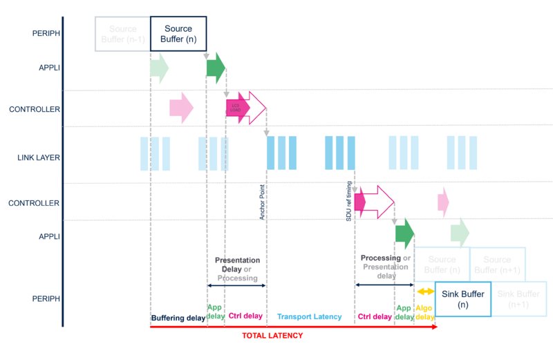
The Bluetooth® Low Energy audio provides a way on mastering the audio latency from the source to the sink. The total audio latency is the sum of the following sub-latencies:
- Buffering delay is the time needed to buffer a frame and is mostly linked to the used codec.
- Algorithmic delay is intrinsic to the codec for ensuring signal continuity during mathematic transformations.
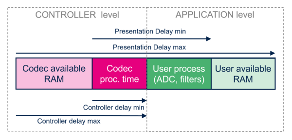
- Presentation delay may be negotiated by profiles within a provided supported range to ensure synchronization of several devices. It can be spat into two subdelays
- Application delay in outside the controller, its minimum is related to the audio processing speed, ADC converter speed, etc ... while its maximum is linked to the resources allocated for buffering.
- Controller delay is inside the controller. Its minimum is related to the codec processing speed and radio preparation time, while its maximum is linked to the resources allocated for buffering.
- Transport latency is introduced by the link layer and correspond to the maximum time for transmitting a packet over the isochronous link. A higher transport latency means more possibilities of retransmitting a packet and a higher quality of service. "While the maximum value is given by the profile to the link layer, the final latency is chosen by the link layer. It can be computed from the ISO stream parameters such as RTN, PHY, BN, etc."
As introduced, the Presentation delay is negotiated by the Bluetooth® Low Energy audio profiles and useful for synchronizing when several servers or broadcast sink are involved. In Unicast, this delay -at server side- is decided by the client using ranges provided by all servers, while in broadcast this value is imposed to the sink. On the client side, we do not have a synchronization constraint and only speak about a Processing delay.
Locally, the device has to split this delay between the Controller delay and the Application delay. This decision is done at the application level based on the range of both delays. The range of controller delay can be read using a standard HCI command, but please note that the application is in charge of recomputing this value if several data paths are superposed.
Creation of the ISO stream is done prior to the establishment of the data path. That means the anchor point of the ISO event is the starting point of all timings and the upper layers have to start audio based on that. Timestamps of the anchor point or SDU reference timings are provided by the link layer. A callback mechanism is provided by the codec manager to trig the audio peripheral -either at source or sink- for ensuring the Controller delay. Then the application is in charge of ensuring the Application delay if this latency is not null.
Typical latencies:
| Use case | Buffering delay | Application delay | Controller delay | Transport latency | Controller delay | Application delay | Algorithmic delay | Total delay |
|---|---|---|---|---|---|---|---|---|
| Phone call, bidirectional at 24kHz, 10 ms frame | 10 ms | ~0 ms | 4 ms | 2.55 ms | 4 ms | 0.1 ms | 2.5 ms | 23.15 ms |
| PBP stereo at 48kHz | 10 ms | 0.1 ms | 22 ms | 13.312 ms | 39.9 ms | 0.1 ms | 2.5 ms | 87.9 ms |
2.4. Codec manager library
2.4.1. Overview
The Codec manager is provided as a library and can be seen as an addon to the controller. When used, this bloc must be linked to the controller, and must be integrated with local resources.
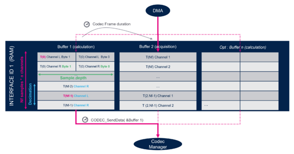
It provides a vendor specific data path on ID 1 that is a RAM with a flexible organization defined by sample depth and decimation parameters. These two parameters must be aligned when configuring the data path through the HCI configure data path command that is using these vendor specific parameters.
Buffers numbers should be at least 2. For example, at the audio source, the first DMA transfer can be used for transferring data. The second (or more) can be given to the codec manager for the the encoding process. This process must run before the DMA erases the data again.
2.4.2. Dependencies
The codec manager relies on the utility stm_queue.c.
The LC3 codec uses some mathematical functions of math.h and the floating-point unit.
2.4.3. Controller interface
BLE_Codec.c file is used for interaction between controller and codec manager. Here, every HCI command related to the codec or data path must be linked.
2.4.3.1. HCI commands
- Codec related commands
- HCI read local supported codecs
- HCI read local supported codec capabilities
- HCI read local supported controller delay
- Data path configuration related command
- HCI configures data path
- Data path commands
- HCI LE setup ISO data path
- HCI LE remove ISO data path
The Codec Manager and the link layer must handle this last category of commands. The controller splits these commands depending on the parameters used.
2.4.3.2. Shunted events
Also the controller shunts some HCI commands and events related to the ISO stream by calling the BLE_IsochronousGroupEvent() function with some parameters. Effectively, the Codec manager expects to be notified of the creation and deletion of the ISO streams using the AUDIO_RegisterGroup() and AUDIO_UnregisterGroup() functions.
2.4.3.3. ISO data
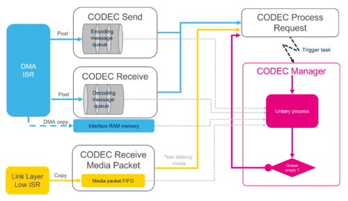
- ISO datum is also exchanged here. Data coming from the link layer are provided from the low ISR context, and must be provided to the codec using CODEC_ReceiveMediaPacket(). On the other direction, the codec calls BLE_SendIsoDataToLinkLayer()
2.4.3.4. Vendor specific synchronization mechanism
And finally, a vendor specific mechanism for synchronization and timings management has to be linked
- HCI vendor specific "synchronization event", containing timestamps related to the ISO group
- The calibration callback - called from the low ISR context - necessary for matching a timestamp from the link layer to the codec clock domain.
2.4.4. Application interface
The application is in charge of initializing the codec manager using the CODEC_ManagerInit() function. This function provides the codec buffers of RAM useful for the LC3 codec inside a structure of type CODEC_LC3Config_t. Also the media_packet_pool is provided here. This pool is necessary for buffering media packets and providing a range of supported controller delay. Finally, we provide here some timings margin to the controller delay, related to either the application or the link layer behavior (radio preparation time). Internal memories and states can be cleaned using the CODEC_ManagerReset().
Function CODEC_RegisterTriggerClbk() allows you to register a callback in each direction to start the audio peripheral (or DMA) at the frame duration rate.
Effectively, CODEC_SendData() and CODEC_ReceiveData() function must then be called every frame duration from the DMA ISR context.
- CODEC_SendData() notify the codec manager that new data is ready to be encoded
- CODEC_ReceiveData() notify the codec manager that a buffer has been played on the peripheral and is ready to be refilled by audio data
Both of these APIs may generate a processing request CODEC_ProcessReq() for asking to run the heavy codec processing by calling CODEC_ManagerProcess().
The internal clock corrector must be initialized, after the PLL has been set up, using the function AUDIO_InitializeClockCorrector() and providing the details of the clock tree, and intervals of calculations. AUDIO_DeinitializeClockCorrector() can be used for resetting the clock corrector.
2.4.5. codec integration
Codec_if.c file is used for allowing the codec manager to access some resources.
2.4.5.1. Processing
CODEC_ProcessInit() and CODEC_ProcessReq(), as seen before, are related to codec processing. Since the codec manager has a real time constraint but still is a heavy CPU load, it is recommended to either execute the codec manager from an interrupt with low priority or a task with high priority.
CODEC_ReqIRQState() function is here for delaying this processing and avoiding the codec to preempt another task. If the codec is delayed, the extra latency must be added to the minimum controller delay as a margin.
2.4.5.2. Audio timer
The codec manager relies on an approximately 1MHz timer. Initialization of this timer can be done inside CODEC_CLK_Init(), which must be called from the application before establishing the ISO stream. The clocking tree of this timer is critical since it is also use for clock synchronization, it absolutely needs to be clocked from the same clock as the audio peripheral, meaning from the PLL output. A dedicated 20-bit audio timer is available in the RCC IP but a general purpose timer could also be used.
The codec manager calls CODEC_CLK_GetHostTimestamp() for getting some timestamp from this clock.
This timer must be free running with the capability of requesting an event on some given timestamp through the CODEC_CLK_RequestTimerEvent() API, then event is then notified with CODEC_CLK_trigger_event_notify() to the codec manager
2.4.5.3. PLL interaction
The PLL corrector needs CODEC_CLK_GetPLLNfrac() and CODEC_CLK_SetPLLNfrac() to be implemented for synchronizing clocks.
2.4.5.4. Debug signal and traces
Depending on the compilation option, some events, or logs can be retrieved in CODEC_TraceEvnt() and CODEC_DBG_Log() functions.
2.4.6. Considerations
2.4.6.1. Radio setup time and controller delay
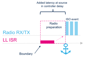
Looking closer at the link layer behavior, we notice it needs time for preparing an event. This additional timing is called radio setup time and any packet given to the link layer inside this preparation window cannot be send immediately and will be delayed of one ISO event.
Thus, this delay is added to the minimum controller delay value based on the given parameters at the codec initialization. This value has to be profiled with the core clock used during audio streaming. As soon as the ISO stream is up, this value can also be retrieved from the aci_hal_sync_event() as the delta between (Next_Anchor_Point - Next_Sdu_Delivery_Timeout).
Considering this, and since the time when the codec manager sends its packets to the link layer is based on the controller delay, it is not recommended to use the value of controller delay at source that may lead to get close to the identified boundary. At the application level that means to avoid (controller_delay - radio_setup_time) % frame_ms ≈ 0
2.4.6.2. Clock tree and Low power
When streaming audio, Sleep mode can be enabled to stop the CPU between encoding and decoding process, however audio peripheral and audio timer must run from PLL without discontinuities.
Looking at the clock tree, clocking the audio from a secondary PLL output (P or Q) allows to reduce SYSCLK during sleep mode without impacting the audio stream, so reduce power consumption. A minimum could be defined by the audio peripheral itself. For example, the SAI requires an APB2 clock that is at least twice as high as the bit rate clock frequency.
3. References
