1. Introduction
Besides offering the STMicroelectronics USB stack, USBX, the Azure® RTOS USB embedded stack is currently supported and offered with a set of applications running on STM32 MCUs.
The Introduction to USB with STM32 article is a dedicated wiki page that provides a general overview of the Universal Serial Bus and its main features.
USBX is the Azure® RTOS USB Host and USB Device embedded stack. It is tightly coupled with ThreadX. In some classes, it requires the FileX and NetX Duo stacks. It allows operation with USB devices with multiple configurations, composite devices, and USB OTG. It supports USB power management.
USBX provides both USB Host and USB Device stacks with a large set of USB classes. The modular architecture makes porting onto different USB hardware IPs easier as soon as the low-level driver can answer the USBX requests.
All the STM32 USB IPs (Host, Device, OTG, high_speed, and full_speed) are supported transparently by USBX through the common STM32 HAL driver API.
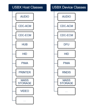
USBX provides all common USB features and classes. The following figure provides the list of currently supported classes:
Besides ThreadX integration with USBX, the USB events are managed through interrupts.
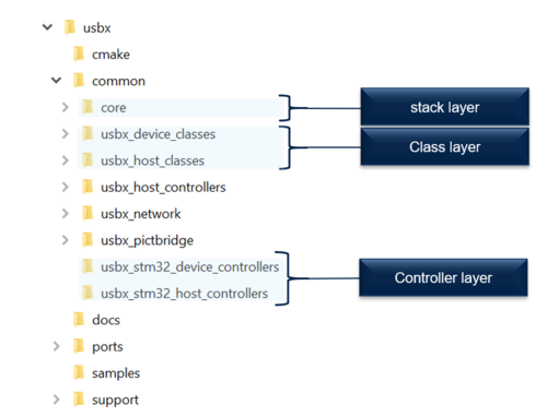
The USBX stack has mainly three layers:
- The lower layer is the controller layer that ensures interfacing with the hardware USB peripheral. For STM32 MCUs, this layer is compatible with the HAL.
- The middle layer ensures the USB stack processing and the interfacing requirements between the low and high layers.
- The higher layer includes the different classes and ensures interfacing with the application layer.
The following figure provides an overview of the USBX three-layer architecture and main components.
As presented in the following figure, the different layers can be easily found within the USBX folder.
2. USBX Device for STM32
This section provides the main guidelines to use the USBX Stack with the HAL on STM32 MCUs.
2.1. STM32 device porting layer
As described in the previous section, USBX is based on three layers that must be referenced within any application project.
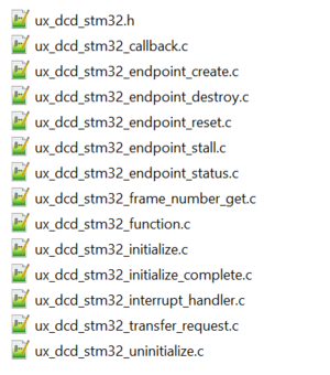
To be able to interface with the STM32 HAL, the project must integrate the STM32 device controllers.
The drivers presented in the figure below include all the APIs allowing interfacing with the STM32 HAL.
2.2. How to customize the USBX Device for STM32
After referencing the required drivers, and depending on the class and application requirements, do the following:
1. Add the convenient descriptors: the device descriptor, the configuration descriptor, the interface descriptor, the endpoint descriptor, and the strings (language ID, product ID, vendor ID, manufacturer, and more).
The following figure shows some of the required definitions for the HID class:
2. Add the class parameters: every class needs to interface with the user application through some variables or functions. Thus, for every class, a structure must be filled before registering the class.
As an example for the HID application, the following structure must be filled in order to be able to register the class:
3. Customize the USBX build options by modifying the status of the different conditional compilation elements defined in the ux_user.h file, such as:
• the USBX thread stack size,
• the maximum class number that can be loaded by USBX,
• the maximum number of devices that can be attached into one USB system,
• the maximum number of endpoints,
• the device used classes,
• the device state side use.
4. Initialize all required peripherals and resources. Depending on the application requirements (UART, I2C and more), all required peripherals must be initialized, generally in the stm32XXxx_hal_msp.c file, where XX corresponds to the family name (For example, h7 or f7).
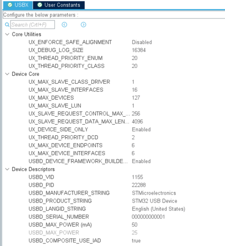
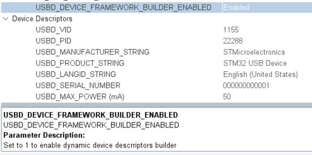
When configuring the project using the STM32CubeMX and the X-CUBE-AZRTOS-XX package, a list of variables can be customized through the interface, before generating a device application.
To see the role of every variable, just click on it. A window shows the description. For instance, "USBD_DEVICE_FRAMEWORK_BUILDER" allows the device framework builder to be enabled or disabled.
2.3. How to use the USBX Device stack to implement an application
1. To start the USBX application, ThreadX must be initialized as described in How to use ThreadX section.
2. Initialize the USBX controller data structures and allocate the required memory.
  /* Initialize USBX Memory & data structures */
  ux_system_initialize(pointer, USBX_MEMORY_SIZE, UX_NULL, 0);
3. Prepare the device, string, and LangID frameworks.
  /* Get_Device_Framework_High_Speed and get the length */
  device_framework_high_speed = USBD_Get_Device_Framework_Speed(USBD_HIGH_SPEED,
                                &device_framework_hs_length);

  /* Get_Device_Framework_Full_Speed and get the length */
  device_framework_full_speed = USBD_Get_Device_Framework_Speed(USBD_FULL_SPEED,
                                &device_framework_fs_length);

  /* Get_String_Framework and get the length */
  string_framework = USBD_Get_String_Framework(&string_framework_length);

  /* Get_Language_Id_Framework and get the length */
  language_id_framework = USBD_Get_Language_Id_Framework(&languge_id_framework_length);
4. Initialize the USBX Device stack with the prepared frameworks.
  /* The code below is required for installation of the device portion of USBX.
  in this application */
  ret =  ux_device_stack_initialize(device_framework_high_speed,
                                    device_framework_hs_length,
                                    device_framework_full_speed,
                                    device_framework_fs_length,
                                    string_framework,
                                    string_framework_length,
                                    language_id_framework,
                                    languge_id_framework_length, UX_NULL);
5. Initialize the device class parameters and register the class.
  /* Initialize the device class. The class is connected with interface 0 in this case */
  ret = ux_device_stack_class_register(_ux_system_slave_class_xxxx_name,
                                       ux_device_class_xxxx_entry, 1, 0, (VOID *)&class_xxxx_parameter);
6. Initialize the USB hardware peripheral and start the controller.
7. Implement the required applications tasks using Threads or Message Queue as explained in How to use ThreadX section.
2.4. USBX Device applications
This section provides an overview of the USBX Device applications offered on STM32 MCUs.
2.4.1. USBX Device application architecture
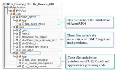
The following figure shows the project architecture and main application files.
2.4.2. USBX Device application overview
The following table provides an overview about the offered USBX Device applications:
| USBX Device application | Overview |
|---|---|
| HID Application | This application makes the STM32 emulate a mouse USB device. When connected to a host through its USB peripheral, the STM32 is detected as an STM32 HID Mouse. The cursor moves automatically. For more details, please refer to the Readme file in the application [2]. This application was implemented according to the Device Class Definition for Human Interface Device (HID) specification [3]. |
| MSC application | This application makes the STM32 emulate a flash disc device. When connected to a host through its USB peripheral, the STM32 is detected as an STM32 mass storage device. The device can then be written, read and formatted. For more details, please refer to the Readme file in the application [4]. This application was implemented according to the Universal Serial Bus Mass Storage Class specification[5]. |
| CDC ACM application | This application makes the STM32 emulate an UART-USB Bridge. When connected to a host through its USB peripheral, the STM32 is detected as an STM32 Virtual Com port. An HyperTerminal can be opened with the detected port and a communication can be established between the STM32 Virtual comport and the STM32 ST-link (UART) port. For more details, please refer to the Readme file in the application [6]. This application was implemented according to the Class definitions for Communication Devices specification[7]. |
| Ux_Device_HID_CDC_ACM | This application provides an example of Azure®RTOS USBX stack usage on STM32H747I_Discovery board, it shows how to develop a composite USB Device communication Class "HID" and "CDC_ACM" based application. The application is designed to emulate an USB HID mouse device and USB-to-UART bridge following the Virtual COM Port (VCP) implementations. For more details, please refer to the Readme file in the application [8]. |
| CDC ECM application | This application shows how to implement an application to run Web HTTP server stack over a USB interface using the CDC-ECM class. When an SD card is inserted into the STM32 board's SD-card reader and the board is powered up and connected to a DHCP-enabled Ethernet network, the green LED switches ON when Web HTTP server is successfully started. For further details, please refer to the Readme file in the application [9]. |
3. USBX Host for STM32
This section provides the main guidelines to use the USBX Host stack with the HAL on STM32 MCUs.
3.1. STM32 host porting layer
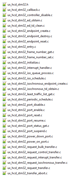
As described in the previous section, the USBX stack is based on three layers that must be referenced within any application project. To be able to interface with the STM32 HAL, the project must integrate the STM32 host controllers interfacing with the HAL layer. The drivers presented in the figure below include all the APIs allowing the interfacing with the STM32 HAL.
3.2. How to customize the USBx Host for STM32
1. Customize the USBX build options by modifying the status of the different conditional compilation elements defined in the ux_user.h file, such as:
• the USBX thread stack size,
• the maximum class number that can be loaded by USBX,
• the maximum number of devices that can be attached into one USB system,
• the maximum number of endpoints,
• the host used classes,
• the host state side use.
2. Depending on the application requirements, the different peripherals and clocks should be correctly defined. Generally, the different peripheral IO initializations are done in the stm32XXxx_hal_msp.c, where XX refers to the STM32 family (For example, h7, f4, or f7).
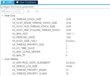
When configuring the project using STM32CubeMX and the X-CUBE-AZRTOS-XX package, a list of variables can be customized through the interface before generating a host application.
To see the role of every variable, just click on it. A little window shows the description.
3.3. How to use the USBX Host stack to implement an application
1. To start the USBX application, ThreadX must be initialized as described in How to use ThreadX section.
2. Initialize the USBX different data structures to be used by the USB system.
  /* Initialize USBX memory. */
  if (ux_system_initialize(pointer, USBX_MEMORY_SIZE, UX_NULL, 0) != UX_SUCCESS)
  {
    ret = UX_ERROR;
  }
3. Register an error callback function to be able to get the error events at application level (this step is optional). This callback is called when an error occurs at thread level or at interrupt level. It can be called to inform the user of the error codes that can be related to the host controller, the device controller, the initialization, the class, the device stack, and more.
  /* register a callback error function */
  _ux_utility_error_callback_register(&ux_host_error_callback);
4. Initialize the USB Host stack.
  /* The code below is required for installing the host portion of USBX.  */
  if (ux_host_stack_initialize(ux_host_event_callback) != UX_SUCCESS)
  {
    status = UX_ERROR;
  }
Device status check: The function ux_host_stack_initialize() allows the initialization of the USB host stack. It takes a change event callback as a parameter, allowing the user application to determine whether the device status is defined. This callback, if required, should be defined at application level. It is called when the device status is modified (inserted, removed, and so on) allowing the user to perform the required process following that event.
5. Register the class.
  /* Register the convenient class. */
  if ((status =  ux_host_stack_class_register(_ux_system_host_class_xxxx_name,
                                              _ux_host_class_xxxx_entry)) != UX_SUCCESS)
  {
    status = UX_ERROR;
  }
6. Initialize the USB hardware peripheral.
7. Register all the available USB Host controllers with the USBX stack.
  /* Register all the USB host controllers available in this system. */
  if (ux_host_stack_hcd_register(_ux_system_host_hcd_stm32_name,
                                 _ux_hcd_stm32_initialize,
                                 USB_OTG_HS_PERIPH_BASE,
                                 (ULONG)&hhcd_USB_OTG_HS) != UX_SUCCESS)
  {
    status = UX_ERROR;
  }
7. Define and create the application required Threads or Message Queue.
8. Start the USB Host controller.
3.4. USBX Host applications
This section provides an overview of the offered USBX Host application.
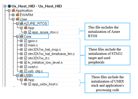
3.4.1. USBX Host application architecture
The following figure shows the USB Host application main files and architecture.
3.4.2. USBX Host application overview
The following table provides an overview of the offered USBX Host applications:
| USBX Host application | Overview |
|---|---|
| HID Application | This application makes the STM32 emulate a USB HID Host that can enumerate and communicate with mice and keyboards. When an HID device (mouse or keyboard) is connected to a host through its USB peripheral, the STM32 detects it, recognizes its types and receives data in real time:
For further details, please refer to the Readme file in the application[10]. |
| MSC Application | This application makes the STM32 emulate a USB mass storage Host that can enumerate and communicate with flash disk USB devices. When a Mass Storage is connected to the STM32 host through its USB peripheral, the STM32 detects the Device, enumerate it, create a file, write and read data and check the data integrity. For more details, please refer to the Readme file in the application [11]. |
| Dual Class Application | This application provides an example of Azure® RTOS USBX stack usage. It shows how to develop a USB Host human interface "HID" and mass storage "MSC" that enumerates and communicates with:
For further details, please refer to the Readme file in the application[12]. |
| CDC ACM Application | This application provides an example of an STM32 USB Host CDC. When a CDC device is plugged into the STM32 Host board through an available port, a message is displayed on the UART HyperTerminal showing some information about the attached device. After the enumeration phase, the Host must be able to properly decode the CDC_ACM class request, and receive and send (from/to) the device. For further details, please refer to the Readme file in the application[13]. |
4. STM32 USB-USBX migration
Commonly for all applications, it is up to the user to initialize the HAL layer through HAL_Init(), the MPU configuration (if required), the system clocks through SystemClock_Config(), and the different hardware peripherals that are used in the application (such as UART/USART, SD card, I2C, and SPI).
4.1. Migration from USBD to USBX Device
USB Device framework builder:
For the STM32 USB applications that are based on the USB Device library, the user only has to register the convenient class in the application. All the class-dependent descriptors (such as configuration and device qualifier descriptors) are provided automatically when requested within the class layer.
For USBX-based applications, it is up to the user to build the required descriptors in the framework. Thus, a dedicated framework builder API has been implemented to make this task easier. In fact, this API ensures the implementation of the required USB descriptors at application level (such as device descriptors, configuration descriptors and specific class descriptors).
The USB Device initialization and configuration are mainly ensured by calling, in the application layer, the APIs described in the table below:
| Application based on STM32 USB Device stack | Application based on USBX Device stack |
|---|---|
| USBD_Init () initializes the device stack and registers the class driver.
Before calling this API, the user must:
|
ux_system_initialize() initializes USBX memory and data structures. ux_device_stack_initialize() initializes the USB Device stack. This API takes as parameters the different frameworks that the user has to define in the application.
|
| USBD_RegisterClass () links the class driver to the device core. The different common descriptors (configuration, qualifier and class descriptors) are provided within the class layer. The user must add the device descriptor. | ux_device_stack_class_register() registers the convenient class with the convenient parameter structures for every class as explained in How to customize section. |
| USBD_Start () starts the USB device core including the device driver (no need to call HAL_PCD_Start() as this was already done inside the USBD_Start() function). | ux_device_stack_pcd_register () initializes the USBX Device stack with the prepared frameworks.
When the initialization is complete, the device driver must be started by calling HAL_PCD_Start() in the application. |
4.2. Migration from USBH to USBX Host
The USB Host initialization and configuration is mainly ensured by calling, in the application layer, the APIs described in the table below:
| Application based on STM32 USB Host stack | Application based on USBX Host stack |
|---|---|
| USBH_Init () initializes the host library and loads the class driver. It includes the USB Host driver initialization by calling HAL_HCD_Init() which, in turn, ensures the USB hardware peripheral initialization by calling the HAL_HCD_MspInit (). This last HAL function must be overloaded by the user at application level, to include the correct initialization (such as USB GPIOs, clock, interrupt enabling and correct priority configuration).
USBH_Init () also ensures the low-level driver parameter initialization (such as speed, DMA enable, low-power enable and PHY interface) by calling USBH_LL_Init(). As a result, this last LL function must be overloaded at application level and then called in the core layer. |
ux_system_initialize() initializes the USBX data structures to be used by the USB system. ux_host_stack_initialize () initializes the USB Host stack. This API takes as parameter a pointer to the host events callback that must be defined by the user (if required).
|
| USBH_RegisterClass () links the class driver to the host core. | ux_host_stack_class_register() registers the convenient class. |
| USBH_Start () starts the USB host core including the Host driver (no need to call HAL_HCD_Start() as this was already done inside the USBH_Start() function). | ux_host_stack_hcd_register () registers all the available USB Host controllers with the USBX stack.
When the initialization is complete, the application must:
|
| USBH_Process() must be called to manage the background process of the USB core. | This process is currently managed through threads with ThreadX. |
5. USBX application implementation using STM32CubeMX
To be able to implement USBX application, please follow the steps below:
5.1. Installation
1. Download STM32CubeMX here[14].
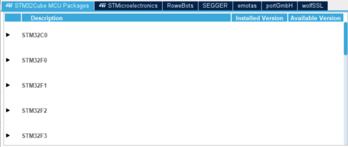
2. Make sure that the convenient STM32Cube software package is installed:
After launching STM32CubeMX, select Install or Remove.
Then select STM32Cube MCU packages. Parse the displayed STM32 series names and select the convenient one.
A list of STM32Cube MCU packages for the selected series is displayed, with checkboxes to select the convenient version.
3. Make sure that the convenient XCube Azure® RTOS package is installed:
After launching STM32CubeMX, select Install or Remove, then select "'STMicroelectronics"'.
Choose the convenient "'X-CUBE-AZRTOS"' pack for the required series.
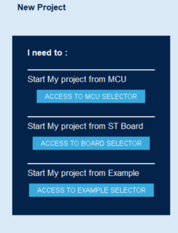
5.2. Creating a new project
Create new project by selecting one of the options below:
- The convenient STM32 MCU
- The convenient STM32 board
- An existing example
Configure the project (such as clocks, hardware IPs and interrupts). For more details, please refer to Introduction to STM32CubeMX
Configure the USB hardware IP (under Connectivity, in STM32CubeMX) by selecting the mode and configuration:
- Mode (Device or Host)
- GPIO settings
- NVIC settings
- Parameters settings
5.3. Configuring the components in the X-CUBE-AZRTOS pack
- Select Software Packs
- Choose Select Components
- Select USB USBX, then USBX, then the CoreSystem component. A yellow triangle appears when double-clicking on it. The component dependencies appear as shown in the figure below:
- As shown in the component dependencies, select the RTOS ThreadX group, then Core component.
5.3.1. For USBX Host applications
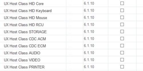
- Select UX Host Controllers under the USB USBX group. Then, resolve all the dependencies by selecting USBX/Ux Host Core Stack and HAL/HCD.
- Select the required classes:
5.3.2. For USBX Device applications
- Select UX Device Controllers, under the USB USBX group.
- Resolve all the dependencies (by selecting USBX/Ux Device Core Stack and HAL/DCD).
- Select the required classes.
5.4. Generating code and finalizing the application implementation
After configuring the system clocks and the required peripherals, and after enabling correctly the different components in the X-CUBE-AZRTOS package:
- Finalize the project configuration in the Project Manager window, and save it.
- Generate by clicking on Generate Code.
- Open the generated application. It will include initialization code and dedicated empty application zones delimited by /* USER CODE BEGIN ... */ and /* USER CODE END ... */ comments to be manually filled by the required application code.
6. References
- ↑ Azure® RTOS USBX documentation
- ↑ This application makes the STM32 emulate a mouse USB device
- ↑ Device Class Definition for Human Interface Devices (HID) specification
- ↑ This application makes the STM32 emulate a Flash disc device
- ↑ Universal Serial Bus Mass Storage Class specification
- ↑ This application makes the STM32 emulate an UART-USB Bridge
- ↑ Class definitions for Communication Devices specification
- ↑ This application provides an example of Azure® RTOS USBX stack usage on STM32H747I_Discovery board
- ↑ This application shows how to implement an application to run Web HTTP server stack over a USB interface using the CDC-ECM class
- ↑ This application makes the STM32 emulate a USB HID Host that can enumerate and communicate with mice and keyboards
- ↑ This application makes the STM32 emulate a USB mass storage Host that can enumerate and communicate with Flash disk USB devices
- ↑ This application provides an example of Azure® RTOS USBX stack usage
- ↑ This application provides an example of an STM32 USB Host CDC
- ↑ STM32CubeMx Download Link
