Registered User mNo edit summary |
Registered User mNo edit summary |
||
| (2 intermediate revisions by 2 users not shown) | |||
| Line 1: | Line 1: | ||
<noinclude>{{ApplicableFor | |||
|MPUs list=STM32MP13x,STM32MP15x | |||
|MPUs checklist=STM32MP13x, STM32MP15x | |||
}}</noinclude> | |||
== Introduction == | == Introduction == | ||
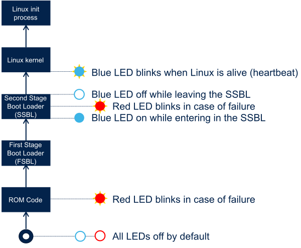
The blue and red [[LEDs and buttons on STM32 MPU boards|LEDs on STM32 MPU boards]] are used to notify the user in case of boot failure during the [[Boot chain overview|boot chain]] execution and at runtime.<br /> | The blue and red [[LEDs and buttons on STM32 MPU boards|LEDs on STM32 MPU boards]] are used to notify the user in case of boot failure during the [[Boot chain overview|boot chain]] execution and at runtime.<br /> | ||
== Description and debug == | == Description and debug == | ||
The statuses of blue and red LEDs allow to see at which stage the execution failed: the diagram below shows how each boot component uses these LEDs while the table gives more information on the way to interpret the LED statuses when the boot fails. Among the boot components, the FSBL | The statuses of blue and red LEDs allow to see at which stage the execution failed: the diagram below shows how each boot component uses these LEDs while the table gives more information on the way to interpret the LED statuses when the boot fails. Among the boot components, the FSBL is TF-A and the SSBL is U-Boot, as explained in the [[Boot chain overview|boot chain overview]]. | ||
<br /><br /> | <br /><br /> | ||
| Line 20: | Line 24: | ||
| Check that:<br /> | | Check that:<br /> | ||
* your microSD card is properly inserted in the board | * your microSD card is properly inserted in the board | ||
* the [[STM32 MPU ROM code overview#Boot device selection | * the [[STM32 MPU ROM code overview#Boot device selection|boot pins]] configuration selects the boot device | ||
* your boot memory was well programmed with [[STM32CubeProgrammer]] | * your boot memory was well programmed with [[STM32CubeProgrammer]] | ||
|- | |- | ||
Latest revision as of 18:49, 24 January 2023
1. Introduction
The blue and red LEDs on STM32 MPU boards are used to notify the user in case of boot failure during the boot chain execution and at runtime.
2. Description and debug
The statuses of blue and red LEDs allow to see at which stage the execution failed: the diagram below shows how each boot component uses these LEDs while the table gives more information on the way to interpret the LED statuses when the boot fails. Among the boot components, the FSBL is TF-A and the SSBL is U-Boot, as explained in the boot chain overview.
| Blue LED | Red LED | System state | Action |
|---|---|---|---|
| Off | Blinking | The execution failed during ROM code execution | Check that:
|
| On | Blinking | The execution failed during the second stage bootloader (SSBL) | See U-Boot - How to debug to investigate the failure |
| Off | Off | The execution may have failed:
|
|
| Off or on | Off | The execution may have failed during Linux® kernel execution between two heartbeat pulses (blue LED): a fatal error leading to a kernel panic might have occurred... | See Dmesg and Linux kernel log to investigate the failure |
| Blinking | Off | Your platform is alive | Enjoy ! |
