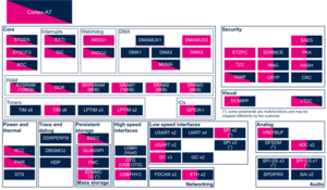
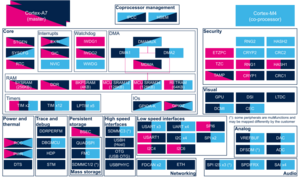
1. Article purpose[edit source]
The purpose of this article is to:
- briefly introduce the ETM peripheral and its main features
- indicate the level of security supported by this hardware block
- explain how each instance can be allocated to the three runtime contexts and linked to the corresponding software components
- explain, when necessary, how to configure the ETM peripheral.
2. Peripheral overview[edit source]
The ETM peripheral is used to log the Cortex®-A7 execution trace into the embedded trace FIFO (ETF). Once in the ETF buffer, the trace can directly be dumped from the Cortex®-A7 or to the trace port interface unit (TPIU), connected to an external probe able to decode it.
This peripheral has two instances, one for each Cortex®-A7 core.
2.1. Features[edit source]
Refer to the STM32MP13 reference manuals or STM32MP15 reference manuals for the complete list of features, and to the software components, introduced below, to see which features are really implemented.
2.2. Security support[edit source]
The ETM is a non secure peripheral.
3. Peripheral usage and associated software[edit source]
3.1. Boot time[edit source]
The ETM can be used to debug the boot sequence using external probe.
3.2. Runtime[edit source]
3.2.1. Overview[edit source]
The ETM can be used to debug the run time application using external probe.
3.2.2. Software frameworks[edit source]
There is no software dedicated to the ETM internal peripheral delivered with STM32MPU ecosystem. Nevertheless, the ETM trace can be captured using an external probe.
3.2.3. Peripheral configuration[edit source]
Configuration of the ETM is done via JTAG scripts. Those scripts must be built by user thanks to STM32MP13 reference manuals or STM32MP15 reference manuals .
3.2.4. Peripheral assignment[edit source]
3.2.4.1. On STM32MP13x lines  [edit source]
Click on the right to expand the legend...
Check boxes illustrate the possible peripheral allocations supported by STM32 MPU Embedded Software:
- ☐ means that the peripheral can be assigned (☑) to the given runtime context.
- ⬚ means that the peripheral can be assigned to the given runtime context, but this configuration is not supported in STM32 MPU Embedded Software distribution.
- ✓ is used for system peripherals that cannot be unchecked because they are statically connected in the device.
Refer to How to assign an internal peripheral to a runtime context for more information on how to assign peripherals manually or via STM32CubeMX.
The present chapter describes STMicroelectronics recommendations or choice of implementation. Additional possiblities might be described in STM32MP13 reference manuals.
| Domain | Peripheral | Runtime allocation | Comment | ||
|---|---|---|---|---|---|
| Instance | Cortex-A7 secure (OP-TEE) |
Cortex-A7 non-secure (Linux) | |||
| Trace & Debug | ETM | ETM | ✓ | ✓ | |
3.2.4.2. On STM32MP15x lines  [edit source]
Click on the right to expand the legend...
Check boxes illustrate the possible peripheral allocations supported by STM32 MPU Embedded Software:
- ☐ means that the peripheral can be assigned (☑) to the given runtime context.
- ⬚ means that the peripheral can be assigned to the given runtime context, but this configuration is not supported in STM32 MPU Embedded Software distribution.
- ✓ is used for system peripherals that cannot be unchecked because they are statically connected in the device.
Refer to How to assign an internal peripheral to a runtime context for more information on how to assign peripherals manually or via STM32CubeMX.
The present chapter describes STMicroelectronics recommendations or choice of implementation. Additional possiblities might be described in STM32MP15 reference manuals.
| Domain | Peripheral | Runtime allocation | Comment | |||
|---|---|---|---|---|---|---|
| Instance | Cortex-A7 secure (OP-TEE) |
Cortex-A7 non-secure (Linux) |
Cortex-M4 (STM32Cube) | |||
| Trace & Debug | ETM | ETM0 | ✓ | ✓ | ||
| ETM1 | ✓ | ✓ | ||||
4. References[edit source]

