Using sensors with B-L475E-IOT01A and with B-U585I-IOT02A![]() 60min
60min
Target description
The purpose of this tutorial is to explain how to perform measurements with the sensors available in the STM32L4 Discovery kit and in the B-U585I-IOT02A Discovery kit. A step by step configuration of the temperature sensor is available.
After this tutorial, you will be able to collect values using the sensors available on the B-L475E-IOT01A board and on the B-U585I-IOT02A board.
The appendix of this tutorial provides guidelines on how to port an AC6 example to STM32CubeIDE.
Prerequisites
You already followed:
Hardware
- STM32L4 Discovery kit IoT node[1] (B-L475E-IOT01A )
- B-U585I-IOT02A Discovery kit IoT node[2] (B-U585I-IOT02A )
- USB cable Type-A to Micro-B
Literature
- UM2153 Discovery kit for IoT node, multi-channel communication with STM32L4
- UM1884 Description of STM32L4/L4+ HAL and low-layer drivers
- UM2839 Discovery kit for IoT node with STM32U5 Series
- UM2911 Description of STM32U5 HAL and low-layer drivers
- UM1859 Getting started with the X-CUBE-MEMS1 motion MEMS and environmental sensor software expansion for STM32Cube
- UM2579 Migration guide from System Workbench to STM32CubeIDE
 Getting started with STM32L4 Discovery kit IoT node
 Discover the new STM32U5 IoT node B-U585-IOT02A Discovery kit
1. Using sensors with B-L475E-IOT01A
1.1. Hardware description
The main sensors available in the STM32L4 Discovery kit IoT node (B-L475E-IOT01A) are:
- Capacitive digital sensor for relative humidity and temperature (HTS221)
- 260-1260 hPa absolute digital output barometer (LPS22HB)
- 3D accelerometer and 3D gyroscope (LSM6DSL)
- High-performance 3-axis magnetometer (LIS3MDL).
1.2. Example: Getting temperature values using the HTS221 sensor and displaying them on a terminal
The purpose of this section is to provide a step by step description on how to interface with the HTS221 sensor to get temperature values and to display them on a terminal.
1.2.1. Create a working project with STM32CubeMX
The starting point is the project generated with STM32CubeMX, described in the Step3 tutorial : Introduction to the UART I/F on B-L475E-IOT01A.
- Follow the steps in the tutorial.
- Name the generated project as L4_IOT_Sensors.
1.2.2. Copy BSP drivers to your project
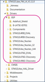
The BSP (board support package) drivers are available in the STM32CubeL4 package. This provides APIs corresponding to the hardware components of a board.
The lastest version of the STM32CubeL4 package is downloaded by default in the STM32CubeMX repository:
C:\Users\user_name\STM32Cube\Repository\STM32Cube_FW_L4_Vx.xx.x.
The image below shows the BSP location and its content:
Follow these steps to copy the BSP drivers to your project:
- In the generated project, create a folder L4_IOT_Sensors/Drivers/BSP.
- Copy the STM32CubeL4/Drivers/BSP/B-L475E-IOT01 folder and paste it in the L4_IOT_Sensors/Drivers/BSP folder.
- Copy the STM32CubeL4/Drivers/BSP/Components folder and paste it under L4_IOT_Sensors/Drivers/BSP/Components.
- Only the HTS221 temperature sensor is used. For this reason, any other files and folders copied to the working directory can be removed. This step is optional:
* Keep only the following files under L4_IOT_Sensors\Drivers\BSP\B-L475E-IOT01:
* Keep only the following files under L4_IOT_Sensors\Drivers\BSP\Components:
1.2.3. Support BSP in STM32CubeIDE workspace
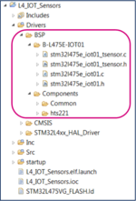
Added folders appear automatically in the STM32CubeIDE workspace:
1.2.4. Update include paths
Update the paths to support new header files:
- Select the relevant project from the Project Explorer perspective:
- From Project menu or File menu, go to Properties > C/C++ Build > Settings > Tool Settings > MCU GCC Compiler > Include paths.
- Click on
 to include the new paths.
 - Add ../Drivers/BSP/B-L475E-IOT01 and ../Drivers/BSP/Components/hts221 paths.
The following screenshot summarizes the steps to follow:

1.2.5. Update source files
Edit main.c as follows:
- Include the header files: stm32l475e_iot01.h, stm32l475e_iot01_tsensor.h and math.h
/* USER CODE BEGIN Includes */
#include "stm32l475e_iot01.h"
#include "stm32l475e_iot01_tsensor.h"
#include <math.h>
/* USER CODE END Includes */
- Add private values. These values are used to display temperature and messages on the terminal:
/* USER CODE BEGIN PV */
/* Private variables -------------------------------------------------------*/
float temp_value = 0;  // Measured temperature value
char str_tmp[100] = ""; // Formatted message to display the temperature value
uint8_t msg1[] = "****** Temperature values measurement ******\n\n\r";
uint8_t msg2[] = "=====> Initialize Temperature sensor HTS221 \r\n";
uint8_t msg3[] = "=====> Temperature sensor HTS221 initialized \r\n ";
/* USER CODE END PV */
- Display messages on the terminal and initialize the HTS221 temperature sensor:
/* USER CODE BEGIN 2 */
HAL_UART_Transmit(&huart1,msg1,sizeof(msg1),1000);
HAL_UART_Transmit(&huart1,msg2,sizeof(msg2),1000);
BSP_TSENSOR_Init();
HAL_UART_Transmit(&huart1,msg3,sizeof(msg3),1000);
/* USER CODE END 2 *//
- In the while (1) loop, read the temperature value, format it, and then display the message with the measured value on the terminal:
/* USER CODE BEGIN 3 */
temp_value = BSP_TSENSOR_ReadTemp();
int tmpInt1 = temp_value;
float tmpFrac = temp_value - tmpInt1;
int tmpInt2 = trunc(tmpFrac * 100);
snprintf(str_tmp,100," TEMPERATURE = %d.%02d\n\r", tmpInt1, tmpInt2);
HAL_UART_Transmit(&huart1,( uint8_t *)str_tmp,sizeof(str_tmp),1000);
HAL_Delay(1000);
/* USER CODE END 3 */
1.2.6. Compile and run the example
- Click on the Build button
 to compile the project.
 - Click on the Debug button
 to run the software.
 - Open a console emulator such as TeraTerm [3]. To configure the console baud rate, select data bits: 8 and click OK. Port name may differ on your computer.
- STM32CubeIDE opens the Debug perspective. Click on the Resume button
 to execute the code.
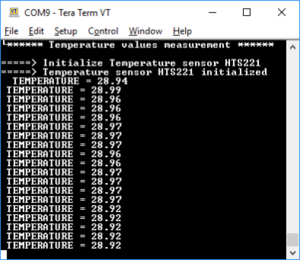
 - TeraTerm [3] displays the initialization message preceding the measured temperature values:
Now you are able to:
- Build your own project to measure temperature values using the embedded sensor in B-L475E-IOT01A.
- Add BSP components to an STM32CubeMx generated project.
- Extend the use of the board to sensors other than HTS221, to make environmental measurements.
2. Using sensors with B-U585-IOT02A
2.1. Hardware description
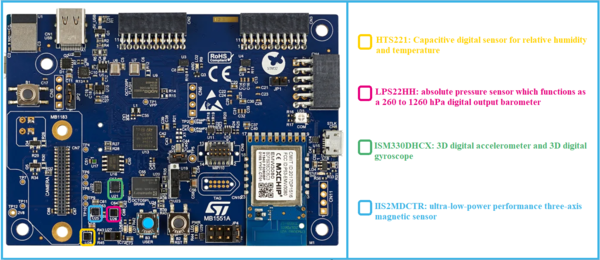
The main sensors available in B-U585I-IOT02A discovery kit for the IoT node are:
- Capacitive digital sensor for relative humidity and temperature (HTS221)
- 260-1260 hPa absolute digital output barometer (LPS22HH)
- 3D accelerometer and 3D gyroscope (ISM330DHCX)
- High-performance 3-axis magnetometer (IIS2MDCTR).
2.2. Example: Getting temperature values using the HTS221 sensor and displaying them on a terminal
The purpose of this section is to provide a step by step description on how to interface with the HTS221 sensor to get temperature values and to display them on a terminal.
2.2.1. Create a working project with STM32CubeMX
Create a new project using STM32CubeMX:
- Select the B-U585I-IOT02A board using the Board selector.
- Answer Yes to Initialize all peripherals with their default Mode ? popup.
- Select without TrustZone activated?. Answer OK to the Create a new project without TrustZone activated? popup.
- Verify in the Pinout tab that the USART1 mode is configured to Asynchronous.
- Click on the USART1 button in the Configuration tab. Set Word Length to 8 Bits, baud rate to 115200 Bits/s, Parity to None and Stop Bits to 1, as shown below:
- Enable ICache in the Pinout tab by selecting Memory address remap to reach the maximum performance.
- Switch to the Project Manager tab: Select STM32CubeIDE as Toolchain/IDE and name your project.
- Click on Generate Code.
- Accept to open the project in STM32CubeIDE and follow the steps.
- Call the generated project U5_IOT_Sensors.
2.2.2. Copy BSP drivers to your project
The BSP (board support package) drivers are available in the STM32CubeU5 package. This provides APIs corresponding to the hardware components of a board.
The lastest version of the STM32CubeU5 package is downloaded by default in the SMT32CubeMX repository:
C:\Users\user_name\STM32Cube\Repository\STM32Cube_FW_U5_Vx.xx.x.
The image below shows the BSP location and its content:
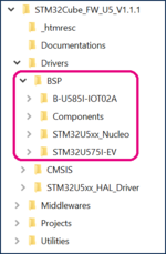
Here are the steps to follow in order to copy the BSP drivers to your project:
- In the generated project, create a folder U5_IOT_Sensors/Drivers/BSP.
- Copy the STM32CubeU5/Drivers/BSP/B-U585-IOT02 folder and paste it to the U5_IOT_Sensors/Drivers/BSP folder.
- Copy the STM32CubeU5/Drivers/BSP/Components folder and paste it under U5_IOT_Sensors/Drivers/BSP/Components.
- Only the HTS221 temperature sensor is used. For this reason, any other files and folders copied to the working directory can be removed. This step is optional:
* Keep only the following folders under U5_IOT_Sensors\Drivers\BSP\Components:
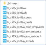
*Keep only the following folders under U5_IOT_Sensors\Drivers\BSP\B-U585-IOT02:
- Rename the file b_u585i_iot02a_conf_template.h to b_u585i_iot02a_conf.h.
2.2.3. Support BSP in STM32CubeIDE workspace
Added folders appear automatically in the STM32CubeIDE workspace:
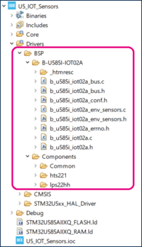
2.2.4. Update include paths
Update the paths to support new header files:
- Select the relevant project from the Project Explorer perspective:
- From Project menu or File menu, go to Properties > C/C++ Build > Settings > Tool Settings > MCU GCC Compiler > Include paths.
- Click on
 to include the new paths.
 - Add the paths ../Drivers/BSP/B-U585I-IOT02A , ../Drivers/BSP/Components/hts221 and ../Drivers/BSP/Components/lps22hh
The following screenshot summarizes the steps to follow:
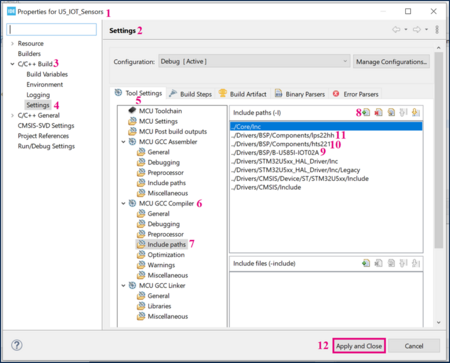
2.2.5. Update source files
Edit main.c as follows:
- Include the header files: b_u585i_iot02a.h, b_u585i_iot02a_env_sensors.h and math.h
/* USER CODE BEGIN Includes */
#include "b_u585i_iot02a.h"
#include "b_u585i_iot02a_env_sensors.h"
#include <math.h>
/* USER CODE END Includes */
- Add private values. These values are used to display temperature and messages on the terminal:
/* USER CODE BEGIN PV */
/* Private variables -------------------------------------------------------*/
float temp_value = 0;  // Measured temperature value
char str_tmp[100] = ""; // Formatted message to display the temperature value
uint8_t msg1[] = "****** Temperature values measurement ******\n\n\r";
uint8_t msg2[] = "=====> Initialize Temperature sensor HTS221 \r\n";
uint8_t msg3[] = "=====> Temperature sensor HTS221 initialized \r\n";
/* USER CODE END PV */
- Display messages on the terminal and initialize the HTS221 temperature sensor:
/* USER CODE BEGIN 2 */
HAL_UART_Transmit(&huart1,msg1,sizeof(msg1),1000);
HAL_UART_Transmit(&huart1,msg2,sizeof(msg2),1000);
BSP_ENV_SENSOR_Init(0, ENV_TEMPERATURE);
BSP_ENV_SENSOR_Enable(0, ENV_TEMPERATURE);
HAL_UART_Transmit(&huart1,msg3,sizeof(msg3),1000);
/* USER CODE END 2 *//
- In the while (1) loop, read the temperature value, format it, and then display the message with the measured value on the terminal:
/* USER CODE BEGIN 3 */
BSP_ENV_SENSOR_GetValue(0, ENV_TEMPERATURE, &temp_value);
int tmpInt1 = temp_value;
float tmpFrac = temp_value - tmpInt1;
int tmpInt2 = trunc(tmpFrac * 100);
snprintf(str_tmp,100," TEMPERATURE = %d.%02d\n\r", tmpInt1, tmpInt2);
HAL_UART_Transmit(&huart1,( uint8_t *)str_tmp,sizeof(str_tmp),1000);
HAL_Delay(1000);
/* USER CODE END 3 */
2.2.6. Compile and run the example
- Click on the Build button
 to compile the project.
 - Click on the Debug button
 to run the software.
 - Open a console emulator such as TeraTerm [3]. To configure the console baud rate, select data bits: 8 and click OK. Port name may differ on your computer.
- STM32CubeIDE opens the Debug perspective. Click on the Resume button
 to execute the code.
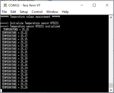
 - TeraTerm [3] displays the initialization message preceding the measured temperature values:
- Build your own project to measure temperature values using the embedded sensor in B-U585I-IOT02A.
- Add BSP components to an STM32CubeMx generated project.
- Extend the use of the board to sensors other than HTS221, to make environmental measurements.
3. Appendix: Porting an AC6 example to STM32CubeIDE
DataLogTerminal is the example used in this appendix.
It is located in: STM32CubeExpansion_MEMS1_V7.1.0\Projects\STM32L476RG-Nucleo\Examples\IKS01A2\DataLogTerminal
3.1. Hardware description
The X-NUCLEO-IKS01A2[4] is a motion MEMS and environmental sensor expansion board for the STM32 64-pin Nucleo. It interfaces with NUCLEO-L476RG via I²C-bus pins.

3.2. Example: Getting temperature values using the HTS221 sensor and displaying them on a terminal (Porting from AC6 to STM32CubeIDE)
The purpose of this section is to provide a step by step description on how to interface the X-NUCLEO IKS01A2 HTS221 sensor and the NUCLEO-L476RG board in order to obtain temperature values and to display them on a terminal.
3.2.1. Hardware setup
- Extend your Nucleo board with the X-NUCLEO-IKS01A2 shield using the Arduino connectors.
- Connect the board with its shield to your computer.
3.2.2. Example details
A description of the DataLogTerminal example is available under STM32CubeExpansion_MEMS1_ V7.1.0\Projects\STM32L476RG-Nucleo\Examples\IKS01A2\DataLogTerminal, in the readme.txt file:
@par Example Description
Main function is to show how to use sensor expansion board to send sensor data from a Nucleo board using UART to a connected PC or desktop, and display it on generic applications like TeraTerm.
After connection has been established:
- The user can view the data from various on-board environment sensors such as temperature, humidity, and pressure
- The user can also view data from various on-board MEMS sensors such as accelerometer, gyroscope, and magnetometer.
3.2.3. Porting the example to STM32CubeIDE
Import the DataLogTerminal example based on SW4STM32 and dedicated to the NUCLEO-L476RG into STM32CubeIDE:
STM32CubeExpansion_MEMS1_V7.1.0\Projects\STM32L476RG-Nucleo\Examples\IKS01A2\DataLogTerminal
The project must be converted and the following message is displayed:
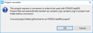
- When clicking on OK, the following message pops up:
- Click OK.
- Select the relevant project from the Project Explorer perspective:
3.2.4. Compiling and running the example
- Click on the Build button
 to compile the project.
 - Click on the Debug arrow
 and select Debug Configurations'.
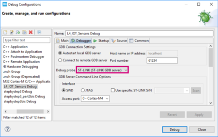
 - In the Debug Configuration window that pops up, make sure that the selected Debug probe is ST-LINK:
- From the same window, click on Debug, or click on the Debug button
 to run the software.
 - Open a console emulator such as TeraTerm [3]. Configure the Console baud rate, select Data bits: 8 and click OK. The port name may differ on your computer.
- Click on the Resume button
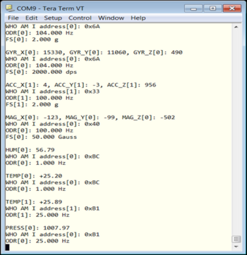
 to execute the code. TeraTerm [3] displays the measured values using the sensors available in the shield X-NUCLEO-IKS01A2.
 - The values measured by the X-NUCLEO-IKS01A2 sensors are displayed in the TeraTerm window as follows:
4. References


