This article provides a description of I3C and explains how to set up an I3C controller using an STM32H5 microcontroller and an IKS01A3 shield board (featuring an LSM6DSO accelerometer/gyroscope and an LPS22HH barometer) as the I3C target.
1. Introduction to I3C
MIPI I3C is a serial communication interface specification that improves upon the features, performance, and power use of I2C, while maintaining backward compatibility for most devices.
An I3C bus controller device drives the push-pull SCL line at the communication bus speed, up to 12.5 MHz.
I3C supports several communication formats, all sharing a two-wire interface. The two wires are designated SDA and SCL:
- SDA (serial data) is a bidirectional data pin, the line on which the controller and the target send or receive the information (sequence of bits).
- SCL (serial clock) is the clock-dedicated line for data flow synchronization.
The purpose of MIPI I3C is threefold:
- Standardize communication inside embedded systems with a reconfigurable bus.
- Reduce the number of physical pins used.
- Support low-power, high-speed data transfer, up to 33 Mbps.
1.1. I3C device types
The I3C bus can be configured with multiple devices. There are four main types of devices:
- I3C main controller.
- I3C secondary controller.
- I3C target.
- Legacy I2C target.
1.2. Features
The I3C bus supports different modes and operations of various message types:
- Broadcast and direct common command code (CCC) messages to communicate with multiple devices or a specific one.
- Dynamic addressing: I3C assigns a dynamic address, unlike I2C, which has a static address.
- Private read/write transfers.
- Legacy I2C messages: the I3C controller can communicate with I2C devices on the I3C bus.
- In-band interrupt (IBI): the target device, connected to the bus, can send an interrupt to the controller over the two-wire (SCL/SDA).
- Hot-join request: the target can join the I3C bus after initialization.
- Controller role request.
1.3. I2C vs I3C
The I3C SDR mode allows only for legacy I2C target devices to coexist with I3C devices on the same I3C bus.
The following table compares the I2C to the I3C interface types.
| Feature | MIPI I3C | I2C |
|---|---|---|
| Bus speed | Up to 12.5 MHz | Up to 1 MHz |
| Signal | Open-drain & push-pull | Open-drain |
| Address | Dynamic address (7 bits) & static address (7 bits) | Static address (7 or 10 bits) |
| Interrupt | In-band interrupt | External I/O |
| Hot join | Yes | No |
| Common command codes (CCC) | Yes | No |
| Clock stretching | No | Yes |
| 9th data bit | Transition bit | ACK or NACK |
| Start, restart & stop conditions | Similar to I2C | - |
2. Setup & demo examples
2.1. Hardware prerequisites
- 1x STM32 Nucleo development board (NUCLEO-H503RB).
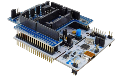
- 1x Motion MEMS and environmental sensor expansion board (X-NUCLEO-IKS01A3).
The X-NUCLEO-IKS01A3 board is compatible with the Arduino® UNO R3 connector layout and features the LSM6DSO 3-axis accelerometer + 3-axis gyroscope, the LIS2MDL 3-axis magnetometer, the LIS2DW12 3-axis accelerometer, the HTS221 humidity and temperature sensor, the LPS22HH pressure sensor, and the STTS751 temperature sensor.
The X-NUCLEO-IKS01A3 interfaces with the STM32 microcontroller via the I2C/I3C pin, and it is possible to change the default I2C/I3C port.
The image below shows an X-NUCLEO-IKS01A3 board plugged into an STM32 Nucleo board.
2.2. Examples
Example 1: assign a dynamic address to the LSM6DSO using ENTDAA (enter dynamic address assignment) CCC - Keep only JP2.
Example 2: assign a dynamic address to the LPS22HH using SETDASA (set dynamic address from static address) CCC - Keep only JP4.
3. Configuring the I3C controller to communicate with I3C targets
3.1. Objective
The goal of this example is to assign a dynamic address using NUCLEO-H503RB as the I3C controller and LSM6DSO and LPS22HH as the targets, with two different modes.
3.2. Creating a project in STM32CubeIDE
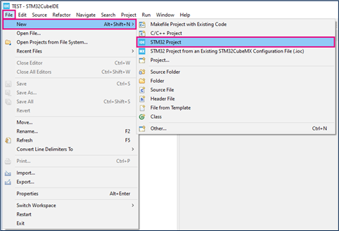
- Go to File > New > STM32 Project in the main window.
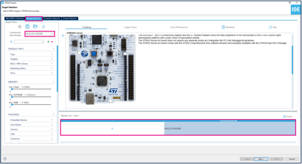
- Select the NUCLEO-H503RB board in the Board Selector tab and click Next, as shown in the figure below.
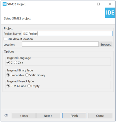
- Save the project.
- Initialize all peripherals with their default settings. Answer “Yes” to "Initialize all peripherals with their default mode?" in the popup window, as shown below.
If you haven't downloaded the STM32CubeH5 library yet, it will now be downloaded automatically. This might take some time.
3.3. Configuring I3C
Open the STM32CubeMX project from the workspace.
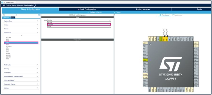
- In Connectivity, select I3C1.
- Select PB6: SCL and PB7: SDA for I3C1.
- Select the Controller mode, as shown below.
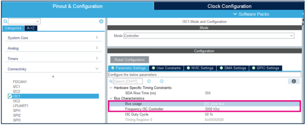
- Set Frequency I3C controller to 3000 kHz, as shown below.
- Select I3C pure bus (there are only I3C devices on the bus).
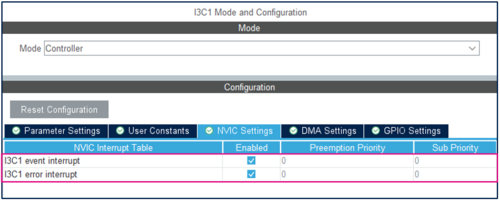
NVIC settings
In the NVIC Settings tab, enable I3C1 event and error interrupt, as shown in the image below.
Clock configuration
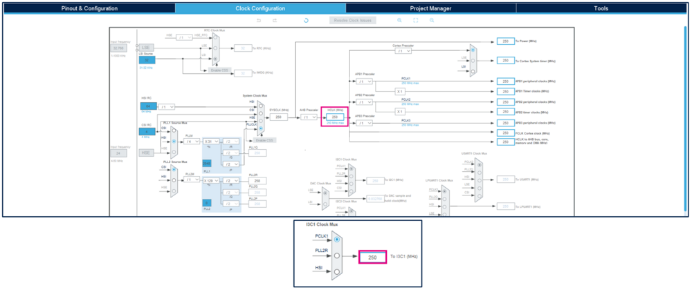
Select the system clock at 250 MHz:
- Select HSI from PLL1 Source Mux.
- Select PLLCLK from System Clock Mux.
- Set HCLK to 250 MHz.
- Select PCLK from the I3C1 Clock Mux.
Check the following values: PLLM = 4, PLLN = 31, PLLP = 2, PLLQ = 2, PLLR = 2, APB1 Prescaler = 1.
3.4. Generating source code and editing main.c
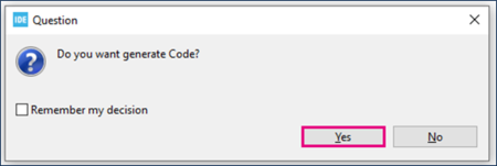
Click "Ctrl + S" to generate the project and click "Yes" in the popup window, as shown below.
4. Software settings
Dynamic addressing can operate in different modes:
- Using ENTDAA CCC (interrupt or blocking mode).
- Using SETDASA CCC.
4.1. Dynamic addressing using ENTDAA CCC (LSM6DSO)
Keep only JP2
- Open main.h in Project Explorer /project_name/Inc/main.h.
- Insert your code between the /* USER CODE BEGIN ET */ and /* USER CODE END ET */ tags, as shown below.
/* USER CODE BEGIN ET */
typedef struct {
  char *        TARGET_NAME;          /*!< Marketing Target reference */
  uint32_t      TARGET_ID;            /*!< Target Identifier on the Bus */
  uint64_t      TARGET_BCR_DCR_PID;   /*!< Concatenation value of PID, BCR and DCR of the target */
  uint8_t       STATIC_ADDR;          /*!< Static Address of the target, value found in the datasheet of the device */
  uint8_t       DYNAMIC_ADDR;         /*!< Dynamic Address of the target preset by software/application */
} TargetDesc_TypeDef;
/* USER CODE END ET */
- Insert the following line:
/* USER CODE BEGIN Private defines */
/* Define Target Identifier */
#define DEVICE_ID1      0U
- Create a new header file target.h in Project Explorer /project_name/Inc/target.h:
/* Define to prevent recursive inclusion -------------------------------------*/
#ifndef __STM32_I3C_DESC_TARGET1_H
#define __STM32_I3C_DESC_TARGET1_H

/* Includes ------------------------------------------------------------------*/
/* Exported types ------------------------------------------------------------*/
/* Exported constants --------------------------------------------------------*/
#define TARGET1_DYN_ADDR        0x32

/********************/
/* Target Descriptor */
/********************/
TargetDesc_TypeDef TargetDesc1 =
{
  "TARGET_ID1",
  DEVICE_ID1,
  0x0000000000000000,
  0x00,
  TARGET1_DYN_ADDR,
};

#endif /* __STM32_I3C_DESC_TARGET1_H */
4.1.1. Interrupt mode
- Open main.c in Project Explorer /project_name/Src/main.c.
- Include the target lib in the project by inserting your code between the /* USER CODE BEGIN Includes */ and /* USER CODE END Includes */ tags, as shown below.
/* USER CODE BEGIN Includes */
#include "target.h"
/* USER CODE END Includes */
- Add the target descriptor by inserting your code between the /* USER CODE BEGIN PV */ and /* USER CODE END PV */ tags, as shown below.
/* USER CODE BEGIN PV */
/* Array contain targets descriptor */
TargetDesc_TypeDef *aTargetDesc[1] = \
                          {
                            &TargetDesc1,       /* DEVICE_ID1 */
                          };
/* Buffer that contain payload data, mean PID, BCR, DCR */
uint8_t aPayloadBuffer[64];
/* USER CODE END PV */
- Then insert the following code between the /* USER CODE BEGIN 2 */ and /* USER CODE END 2 */ tags, as shown below.
/* USER CODE BEGIN 2 */
  /* Assign dynamic address processus ## Initiate a RSTDAA before a ENTDAA procedure ##*/
  if (HAL_I3C_Ctrl_DynAddrAssign_IT(&hi3c1, I3C_RSTDAA_THEN_ENTDAA) != HAL_OK)
  {
    Error_Handler();
  }
/* USER CODE END 2 */
- For callback, insert the following code between the /* USER CODE BEGIN 4 */ and /* USER CODE END 4 */ tags.
/* USER CODE BEGIN 4 */
void HAL_I3C_TgtReqDynamicAddrCallback(I3C_HandleTypeDef *hi3c, uint64_t targetPayload)
{
  TargetDesc1.TARGET_BCR_DCR_PID = targetPayload;
  HAL_I3C_Ctrl_SetDynAddr(hi3c, TargetDesc1.DYNAMIC_ADDR);
}
void HAL_I3C_CtrlDAACpltCallback(I3C_HandleTypeDef *hi3c)
{
  HAL_GPIO_WritePin(GPIOA, GPIO_PIN_5, GPIO_PIN_SET);
}
/* USER CODE END 4 */
4.1.2. Blocking mode
- Open main.c in Project Explorer /project_name/Src/main.c.
- Include the target lib in the project by inserting your code between the /* USER CODE BEGIN Includes */ and /* USER CODE END Includes */ tags, as shown below.
/* USER CODE BEGIN Includes */
#include "target.h"
/* USER CODE END Includes */
- Insert your code between the /* USER CODE BEGIN 2 */ and /* USER CODE END 2 */ tags.
/* USER CODE BEGIN 2 */
/* Buffer that contain payload data, mean PID, BCR, DCR */
uint64_t TargetPayload;
uint8_t dynamic_adr = 0x32;
HAL_StatusTypeDef status = HAL_OK;

/* Assign dynamic address processus */
      do
      {
         status = HAL_I3C_Ctrl_DynAddrAssign(&hi3c1, &TargetPayload, I3C_RSTDAA_THEN_ENTDAA, 5000);
        if (status == HAL_BUSY)
        {
          HAL_I3C_Ctrl_SetDynAddr(&hi3c1, dynamic_adr);
        }
      } while (status == HAL_BUSY);

/* USER CODE END 2 */
4.2. Dynamic addressing using SETDASA CCC (LPS22HH)
Keep only JP4
- Open main.c in Project Explorer /project_name/Src/main.c.
- Insert your code between the /* USER CODE BEGIN PTD */ and /* USER CODE END PTD */ tags, as shown below.
/* USER CODE BEGIN PTD */
#define Direct_SETDASA 0x87
#define Brodacast_DISEC 0x01
#define Brodacast_RST 0x06

#define LPS22HH_DYNAMIC_ADDR 0x32
/* USER CODE END PTD */
- Insert the following code between the /* USER CODE BEGIN PD */ and /* USER CODE END PD */ tags.
/* USER CODE BEGIN PD */
#define I3C_IDX_FRAME_1         0U  /* Index of Frame 1 */
#define I3C_IDX_FRAME_2         1U  /* Index of Frame 2 */
#define STATIC_ADRESS_LPS22HH   0x5D
/* USER CODE END PD */
- Insert the following code between the /* USER CODE BEGIN PV */ and /* USER CODE END PV */ tags.
/* USER CODE BEGIN PV */
uint8_t aSETDASA_LPS22HH_data[1]   = {(LPS22HH_DYNAMIC_ADDR << 1)};
uint8_t aDISEC_data[1]   = {0x08}; // Disable IBI interrupt

/* Buffer used for transmission */
uint8_t aTxBuffer[0x0F];

/* Buffer used by HAL to compute control data for the Private Communication */
uint32_t aControlBuffer[0xF];

/* Context buffer related to Frame context, contain different buffer value for a communication */
I3C_XferTypeDef aContextBuffers[2];

/* Descriptor for direct write SETDASA CCC */
I3C_CCCTypeDef aSET_DASA_LPS22HH[] =
{
    /*Target Addr CCC Value CCC data + defbyte pointer  CCC size + defbyte Direction        */
    {0x5D,Direct_SETDASA,{aSETDASA_LPS22HH_data,1},HAL_I3C_DIRECTION_WRITE},
};

/* Descriptor for direct write DISEC CCC */
I3C_CCCTypeDef aSET_CCC_DISEC[] =
{
    {0x5D,Brodacast_DISEC, {aDISEC_data,1},LL_I3C_DIRECTION_WRITE},
};

/* Descriptor for direct write RST CCC */
I3C_CCCTypeDef aSET_CCC_RST[] =
{
    {0x5D,Brodacast_RST, {NULL,0},LL_I3C_DIRECTION_WRITE},
};
/* USER CODE END PV */
- Insert the following code between the /* USER CODE BEGIN 2 */ and /* USER CODE END 2 */ tags.
/* USER CODE BEGIN 2 */

/* Send a DISEC to disable IBI interrupt */
  aContextBuffers[I3C_IDX_FRAME_1].CtrlBuf.pBuffer = aControlBuffer;
  aContextBuffers[I3C_IDX_FRAME_1].CtrlBuf.Size    = 1;
  aContextBuffers[I3C_IDX_FRAME_1].TxBuf.pBuffer   = aTxBuffer;
  aContextBuffers[I3C_IDX_FRAME_1].TxBuf.Size      = 1;

  /* Add context buffer Set CCC frame in Frame context */
  if (HAL_I3C_AddDescToFrame(&hi3c1,
                             aSET_CCC_DISEC,
                             NULL,
                             aContextBuffers,
                             1,
                             I3C_BROADCAST_WITHOUT_DEFBYTE_RESTART) != HAL_OK)
  {
    Error_Handler();
  }

  if (HAL_I3C_Ctrl_TransmitCCC(&hi3c1, aContextBuffers, 1000) != HAL_OK)
  {
    Error_Handler();
  }

  while (HAL_I3C_GetState(&hi3c1) != HAL_I3C_STATE_READY)
  {
  }

  /* Send a RSTDAA to reset previous dynamic address the target */
  aContextBuffers[I3C_IDX_FRAME_1].CtrlBuf.pBuffer = aControlBuffer;
  aContextBuffers[I3C_IDX_FRAME_1].CtrlBuf.Size    = 1;
  aContextBuffers[I3C_IDX_FRAME_1].TxBuf.pBuffer   = aTxBuffer;
  aContextBuffers[I3C_IDX_FRAME_1].TxBuf.Size      = 1;

  /*Add context buffer Set CCC frame in Frame context */
  if (HAL_I3C_AddDescToFrame(&hi3c1,
                             aSET_CCC_RST,
                             NULL,
                             aContextBuffers,
                             1,
                             I3C_BROADCAST_WITHOUT_DEFBYTE_RESTART) != HAL_OK)
  {
    Error_Handler();
  }

  if (HAL_I3C_Ctrl_TransmitCCC(&hi3c1, aContextBuffers, 1000) != HAL_OK)
  {
    Error_Handler();
  }

  while (HAL_I3C_GetState(&hi3c1) != HAL_I3C_STATE_READY)
  {
  }

  /* Send a SETDASA to set the dynamic on LPS22HH using his static address */
  aContextBuffers[I3C_IDX_FRAME_1].CtrlBuf.pBuffer = aControlBuffer;
  aContextBuffers[I3C_IDX_FRAME_1].CtrlBuf.Size    = 1;
  aContextBuffers[I3C_IDX_FRAME_1].TxBuf.pBuffer   = aTxBuffer;
  aContextBuffers[I3C_IDX_FRAME_1].TxBuf.Size      = 1;

  /* Add context buffer Set CCC frame in Frame context */
  if (HAL_I3C_AddDescToFrame(&hi3c1,
                             aSET_DASA_LPS22HH,
                             NULL,
                             &aContextBuffers[I3C_IDX_FRAME_1],
                             1,
                             I3C_DIRECT_WITHOUT_DEFBYTE_RESTART) != HAL_OK)
  {
    Error_Handler();
  }

  if (HAL_I3C_Ctrl_TransmitCCC_IT(&hi3c1, &aContextBuffers[I3C_IDX_FRAME_1]) != HAL_OK)
  {
    Error_Handler();
  }

  while (HAL_I3C_GetState(&hi3c1) != HAL_I3C_STATE_READY)
  {
  }

  /* After a dynamic address has been assigned, the sensor is recognized as an I3C device */
  /* Check if the LPS22HH sensor is ready to communicate in I3C */
  if (HAL_I3C_Ctrl_IsDeviceI3C_Ready(&hi3c1, LPS22HH_DYNAMIC_ADDR, 300, 1000) != HAL_OK)
  {
    Error_Handler();
  }

/* USER CODE END 2 */
4.3. Compilation, debug, and execution
- Click on the Build button.

- Click on the Debug button
 for a step-by-step run or on the Run button
  to execute.
4.4. Results
4.4.1. Results for LSM6DSO as target
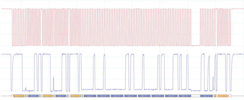
We can check this example by verifying the SDA and SCL behavior with an oscilloscope, as shown below (LSM6DSO using ENTDAA CCC).
From the LSM6DSO datasheet:
- Device ID register PID: 0x0208006C100B.
- Bus characteristics register BCR: 0x07.
- Device characteristics register DCR: 0x44.
4.4.2. Results for LPS22HH as target
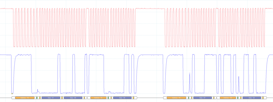
We can check this example by verifying the SDA and SCL behavior with an oscilloscope, as shown below (LPS22HH using SETDASA CCC).
- Broadcast DISEC CCC: 0x01 (0x08: disable IBI interrupt).
- Reset a previous dynamic address: broadcast RSTDAA 0x06.
- Set dynamic address using static address: direct SETDASA 0x87 (dynamic address: 0x32).
5. References
- AN5879: Introduction to I3C for STM32H5 series MCU
- RM0492: STM32H503xx reference manual
- DS12140: LSM6DSO datasheet

