Registered User mNo edit summary |
Registered User mNo edit summary |
||
| (3 intermediate revisions by the same user not shown) | |||
| Line 1: | Line 1: | ||
MB1263 board overview. | |||
== Board overview == | == Board overview == | ||
'''Daughterboard MB1263''' (STM32MP157x 18x18 with PMIC and DDR3), revision C-0.1: part of the | '''Daughterboard MB1263''' (STM32MP157x 18x18 with PMIC and DDR3), revision C-0.1: part of the {{Board | type=157x-EV1}}. | ||
{{ | {{ | ||
| Line 26: | Line 21: | ||
rect 415 84 472 106 [[#LED 6 | ST-LINK/V2-1 LED (bicolor LD6)]] | rect 415 84 472 106 [[#LED 6 | ST-LINK/V2-1 LED (bicolor LD6)]] | ||
rect 380 106 472 156 [[#ST-LINK USB | USB micro-B (ST-LINK/V2-1)]] | rect 380 106 472 156 [[#ST-LINK USB | USB micro-B (ST-LINK/V2-1)]] | ||
rect 130 252 251 374 [[#STM32MP157x | | rect 130 252 251 374 [[#STM32MP157x | STM32MP157x 18x18]] | ||
rect 291 274 363 348 [[#eMMC | eMMC]] | rect 291 274 363 348 [[#eMMC | eMMC]] | ||
rect 130 395 204 614 [[#DDR3L | 2 x DDR3L 16 bits]] | rect 130 395 204 614 [[#DDR3L | 2 x DDR3L 16 bits]] | ||
| Line 47: | Line 42: | ||
== Links == | == Links == | ||
[[STM32MP15 resources#MB1263 schematics|MB1263 schematics]] | [[STM32MP15 resources#MB1263 schematics|MB1263 schematics]] | ||
<noinclude> | |||
{{PublicationRequestId | 7568 | 2018-06-19 | AlainF}} | |||
[[Category:STM32MP15 Evaluation boards]] | |||
[[Category:STM32MP15]] | |||
[[Category:ST boards]] | |||
</noinclude> | |||
Latest revision as of 12:52, 15 June 2020
MB1263 board overview.
1. Board overview
Daughterboard MB1263 (STM32MP157x 18x18 with PMIC and DDR3), revision C-0.1: part of the STM32MP157x-EV1 Evaluation board ![]() .
.
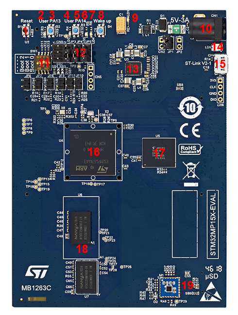
- Reset button
- User LED (red LD2)
- User button (PA13)
- User LED (green LD3)
- User button (PA14)
- User LED (blue LD5)
- User LED (orange LD4)
- Wakeup button
- Power LED (green LD1)
- Power 5V-3A
- Boot mode selection
- Jumpers to connect the UART4 to the ST-LINK/V2-1 or to the mother board USB micro-AB
- PMIC (STPMIC1A)
- ST-LINK/V2-1 LED (bicolor LD6)
- USB micro-B (ST-LINK/V2-1)
- STM32MP157x 18x18
- eMMC
- 2 x DDR3L 16 bits
- microSD 3.0 card
Details of some LEDs:
- LD1: green if power connection established
- LD6: red flashing if ST-LINK/V2-1 connection not established, else green
- LD2, LD3, LD4, LD5: some user LEDs are used to reflect the system activity, whereas the others are left free and can be directly used by the application, as explained in the LEDs and buttons on STM32 MPU boards article
2. Links