Target description
- This tutorial's first part enables you to:
- Use the embedded STM32F769I-DISCO microphones
- Capture the sound got from the microphones
- Expose the complete chain to filter the sound using the DFSDM functionality
- Record the sound and re-listen to them on the output line of the STM32F769I-DISCO using an earphone
- This tutorial's second part enables you to:
- Apply the cross-correlation algorithm to estimate the direction of the sound
Prerequisites
- Computer with Windows 7 (or higher)
Hardware
- 32F769IDISCOVERY[1]
- USB cable Type-A to Micro-B
- Headphones \ Earphones
Software
Literature
- STM32F769NI MCU User Manual[4]
- STM32 DFSDM[5]
- STM32F769xx Datasheet[6]
 Getting started with STM32F769NI discovery kit.
 Recognition of direction of audio stream.
- STM32F769I-DISCO schematics[7]
1. First Capturing sound and recording it
1.1. Installation of the software tools
In this part, the software we will be working on are STM32CubeIDE and STM32CubeMX.
To follow the installation instructions, please refer to this wiki page Tools installation.
1.2. Launching the project
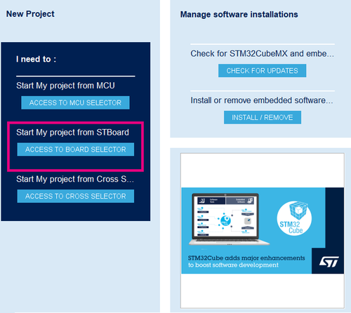
To create the project, please launch STM32CubeMX, and on the home page, click on Access to board selector

Use the Part Number Search field to select specific board STM32F769I-DISCO, as presented in the following image.

1.3. Configuring the board
The next step is to set the right parameters to create the first recording and listening to the sound got from the embedded STM32F769I-DISCO microphones.
Let's start configuring the DFSDM channels and filters.
For the Channel 1, please set the following parameters :
- Mode: Input from ch1 and internal clock as entry
- Channel 1 parameters:
- Right bit shift: 2
- Analog watchdog parameters:
- Oversampling 10
- Output clock:
- Selection : Source for output clock is audio clock
- Divider = 4
For the Channel 0, please set the following parameters :
- Mode : input from CH0 and Internal Clock
- Channel 0 parameters:
- Type SPI with falling edge
- SPI Clock: Internal SPI clock
- Right bit shift: 2
- Analog watchdog parameters:
- Oversampling: 10
- Output clock:
- Selection : audio clock
- Divider = 4

Later, let's configure the filters used.
For the filter 0, please set the following parameters:
- Regular channel selection:
- Regular channel section: Channel1
- Trigger to start regular conversion: Software trigger
- Fast mode: Enable
- Injected channel selection:
- Channel1 as injected channel: Enable
- Trigger to start injected conversion: Software trigger
- Filter parameters:
- Sinc Order: Sinc 3 filter type
- Fosr: 64
For the filter 1, please set the following parameters:
- Regular channel selection:
- Regular channel section: Channel1
- Trigger to start regular conversion: Synchronous with DFSDM0
- Fast mode: Enable
- Injected channel selection:
- Channel0 as injected channel: Enable
- Trigger to start injected conversion: Software trigger
- Scan Mode: Enable
- Filter parameters:
- Sinc Order: Sinc 3 filter type
- Fosr: 64
Now it is time to configure the SAI peripheral.
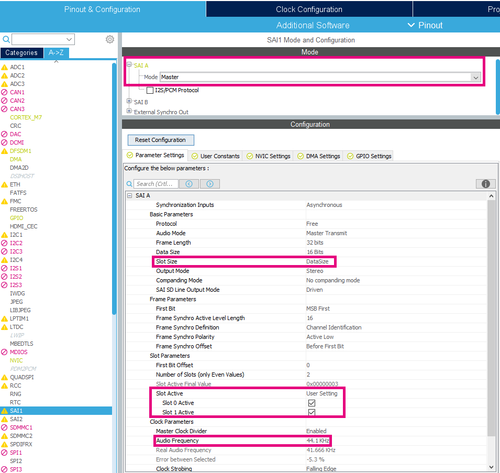
In the Pinout & Configuration tab, click SAI to reveal the Mode and Configuration panels and configure the SAI parameters with the following parameters:
- Audio frequency = 44
- Slot size = datasize
- Slot active = user setting: 0&1

From the Project Manager view, configure the project settings: rename the application, choose STM32CubeIDE as toolchain and click on Generate code.
Once launching the project, follow these steps to create the application:
- Create a new folder in the project's directory in the Drivers folder and name it BSP.
- From the STM32CubeF7 MCU package downloaded from STM32CubeMX, copy the Components folder placed in the directory: C:\Users\UserName\STM32Cube\Repository\STM32Cube_FW_F7_V1.16.0\Drivers\BSP and paste it in the BSP folder in the project's directory.
- Create a new folder in the BSP one named STM32F769I-Discovery and copy the two files : stm32f769i_discovery.c and its header file stm32f769i_discovery.h from the directory: C:\Users\UserName\STM32Cube\Repository\STM32Cube_FW_F7_V1.16.0\Drivers\BSP\STM32F769I-Discovery and place them in the STM32F769I-Discovery folder.
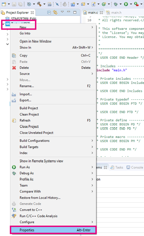
- From Project menu or File menu, go to Properties > C/C++ Build > Settings > Tool Settings > MCU GCC Compiler > Include paths
- Add the following includes as presented in the following photo :
- In the main.h file add the following includes:
#include "stm32f7xx_hal.h"
#include "stm32f769i_discovery.h"
#include "../Components/Common/audio.h"
#include "../Components/wm8994/wm8994.h"
In the main.c file add the following declarations:
#define SaturaLH(N, L, H) (((N)<(L))?(L):(((N)>(H))?(H):(N)))
int32_t                      LeftRecBuff[2048];
int32_t                      RightRecBuff[2048];
int16_t                      PlayBuff[4096];
uint32_t                     DmaLeftRecHalfBuffCplt  = 0;
uint32_t                     DmaLeftRecBuffCplt      = 0;
uint32_t                     DmaRightRecHalfBuffCplt = 0;
uint32_t                     DmaRightRecBuffCplt     = 0;
uint32_t                     PlaybackStarted         = 0;
AUDIO_DrvTypeDef            *audio_drv;
- Add the following function code:
void HAL_DFSDM_FilterRegConvHalfCpltCallback(DFSDM_Filter_HandleTypeDef *hdfsdm_filter)
{
  if(hdfsdm_filter == &hdfsdm1_filter0)
  {
    DmaLeftRecHalfBuffCplt = 1;
  }
  else
  {
    DmaRightRecHalfBuffCplt = 1;
  }
}
In the initialization function of the SAI, add the following code that reads the signal from the microphone device: WM899, initialize audio driver */
 if(WM8994_ID != wm8994_drv.ReadID(AUDIO_I2C_ADDRESS))
    {
      Error_Handler();
    }

    audio_drv = &wm8994_drv;
    audio_drv->Reset(AUDIO_I2C_ADDRESS);
    if(0 != audio_drv->Init(AUDIO_I2C_ADDRESS, OUTPUT_DEVICE_HEADPHONE, 100, AUDIO_FREQUENCY_22K))
    {
      Error_Handler();
    }
- After declaring i as uint32_t, in the While loop, add the following code:
if((DmaLeftRecHalfBuffCplt == 1) && (DmaRightRecHalfBuffCplt == 1))
	    {
	    	for(i = 0; i < 1024; i++)
	    	{
	    		PlayBuff[2*i]     = SaturaLH((LeftRecBuff[i] >> 8), -32768, 32767);
	    		PlayBuff[(2*i)+1] = SaturaLH((RightRecBuff[i] >> 8), -32768, 32767);
	    	}
	    	if(PlaybackStarted == 0)
	    	{
	    		if(0 != audio_drv->Play(AUDIO_I2C_ADDRESS, (uint16_t *) &PlayBuff[0], 4096))
	    		{
	    			Error_Handler();
	    		}
	    		if(HAL_OK != HAL_SAI_Transmit_DMA(&hsai_BlockA1, (uint8_t *) &PlayBuff[0], 4096))
	    		{
	    			Error_Handler();
	    		}
	    		PlaybackStarted = 1;
	    	}
	    	DmaLeftRecHalfBuffCplt  = 0;
	    	DmaRightRecHalfBuffCplt = 0;
	    }
	    if((DmaLeftRecBuffCplt == 1) && (DmaRightRecBuffCplt == 1))
	    {
	    	for(i = 1024; i < 2048; i++)
	    	{
	    		PlayBuff[2*i]     = SaturaLH((LeftRecBuff[i] >> 8), -32768, 32767);
	    		PlayBuff[(2*i)+1] = SaturaLH((RightRecBuff[i] >> 8), -32768, 32767);
	    	}
	    	DmaLeftRecBuffCplt  = 0;
	    	DmaRightRecBuffCplt = 0;
	    }
After finishing the code part, click on Build and later Debug the program.
Put your earphones in the Output audio line jack and enjoy!
2. Second Analog App Based on the cross-correlation algorithm
2.1. Presenting the Algorithm and Setting the formula
In this part of the tutorial, the application will be based on the Cross Correlation Algorithm to track the movements of the two signals got from the two microphones of the board.
The algorithm might be implemented basically on its formula: ∑((x(i)-mx)*(y(i)-my)/√(∑(x(i)-mx)²*√(∑(y(i)-my)²*
In our case the variables :
- x(i) is the signal got from the RightFilter
- y(i) represents the LeftFilter.
- r is the correlation factor which is the angle to calculate
2.2. Adding the code part
To calculate the correlation formula, please keep the previous part of the tutorial and add the following declaration in the main file:
#include <math.h>
int k,j;
double coeff=0;
double mright=0;
double mleft=0;
double sright=0;
double sleft=0;
double sxy,denom;
int n=2048;
int maxdelay=1024;
Now, it is time to set the code calculating the r factor, so to write a code to apply the formula previously mentioned, please add the following code in the While loop:
 for(k = 0; k < n; k++)
     {
    	mright += RightRecBuff[k];
        mleft += LeftRecBuff[k];
     }
     mright /= n;
     mleft /= n;
     /* Calculate the denominator */
     for (k=0;k<n;k++)
     {
        sright += (RightRecBuff[k] - mright) * (RightRecBuff[k] - mright);
        sleft += (LeftRecBuff[k] - mleft) * (LeftRecBuff[k] - mleft);
     }
     denom = sqrt(sright*sleft);
     /* Calculate the correlation series */
     for (delay=-maxdelay;delay<maxdelay;delay++)
       {
           sxy = 0;
           for (k=0;k<n;k++)
           {
              j = k + delay;
              while (j < 0)
              {
        	      j += n;
        	      j %= n;
        	      sxy += (RightRecBuff[k] - mright) * (LeftRecBuff[j] - mleft);
              }
            coeff = sxy / denom; /* r is the correlation coefficient at "delay" */
        }
   }
2.3. References

