| Coming soon |
This article explains what WDOG is and how to use it through examples
1. What is a WDG ?
WDG stands for Watch DOG. The main goal of this IP is to detect and resolve malfunctions due to software failures. The principle is to periodically refresh the WDG (or pet the dog), if the counter isn't refreshed, a system reset is generated. Also, the WDG acts as a protection since it avoids to stay stuck in a particular stage of processing. The configuration using option bytes can launch the WDG by hardware or software. Once enabled, it can only be disabled by a reset
2. WDOG type
There are two types of WDOG :
- WWDG : Window watchdog
- IWDG : Independent watchdog
2.1. WWDG : Window watchdog
2.1.1. Definition
The window watchdog is based on a 7-bit downcounter that can be set as free running. It can be used as a watchdog to reset the device when a problem occurs. It is clocked from the main clock. It has an early warning interrupt capability and the counter can be frozen in debug mode.
2.1.2. Application benefits
- Best suited for applications which require the watchdog to react within an accurate time window.
- Configurable time-window thanks to the prescaler value (For example, the STM32L476xx have a programmable timeout range from 51.2 us to 28.2ms)
- Selectable hardware or software start
- Early Wakeup Interrupt (EWI) available before reset happens
2.1.3. How does it work ?
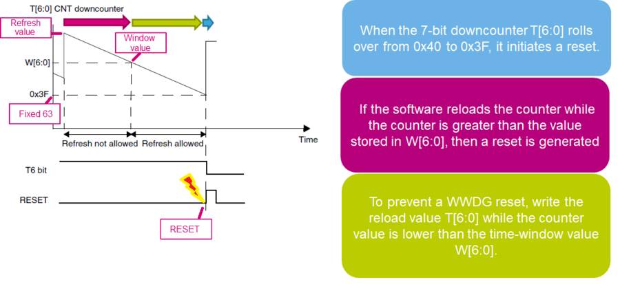
The diagram below illustrates how the WWDG operates. If the downcounter is reloaded too early or too late, the window watchdog will initiate a reset.
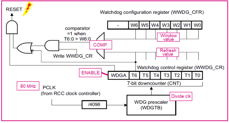
As we can see on the following block diagram, the counter value and the window value are compared in order to evaluate the time to refresh the downcounter in the configurable window.
2.2. IWDG : Independent WatchDoG
2.2.1. Definition
The independent watchdog is based on a 12-bit downcounter and 8-bit prescaler. It is clocked from an independent 32 kHz internal RC (LSI) and as it operates independently from the main clock, it can operate in Stop and Standby modes. It can be used either as a watchdog to reset the device when a problem occurs, or as a free running timer for application timeout management. It is hardware or software configurable through the option bytes. The counter can be frozen in debug mode.
2.2.2. Application benefits
- Totally independent process outside the main application
- Configurable timeout period thanks to the prescaler value (For example, the STM32L476xx have a programmable timeout range from 125us to 32.7s)
- Selectable hardware or software start
- Selectable low-power freeze in Standbye or Stop modes
2.2.3. How does it work ?
The IWDG architecture is represented below :
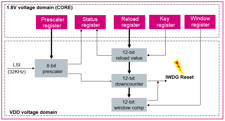
As we can see on the block diagram above, IWDG registers are located in the CORE voltage domain while its functions are in the VDD voltage domain. The 8-bit prescaler is used to divide the LSI oscillator frequency. When the IWDG is started, the 12-bit counter starts counting down from the reset value of 0xFFF. To refresh the IWDG counter, the Key value (0xAAAA) must be written in the Key register to reload the counter value. If the downcounter reaches the end of the count value (0x000), a system reset is generated.
3. Configure WWDG with LED indication
3.1. Objective
- In this project, you will learn how to setup WWDG in STM32CubeIDE
- How to Generate Code in STM32CubeIDE and use HAL functions
- Create a simple application to test and periodically refresh the WWDG
- Verify the correct functionality on toggling LED
3.2. Create the project in STM32ubeIDE
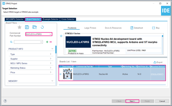
File > New > STM32 Project in main panel.
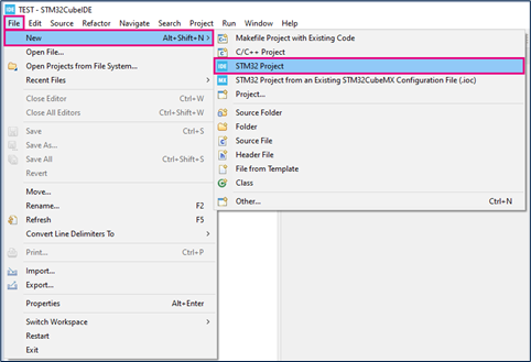
In this example the NUCLEO-L476RG board is used.
- Select NUCLEO-L476RG in board Selector.
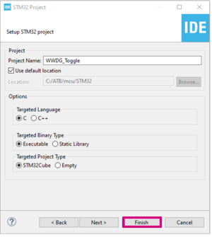
- Save the project.
3.3. GPIO Configuration
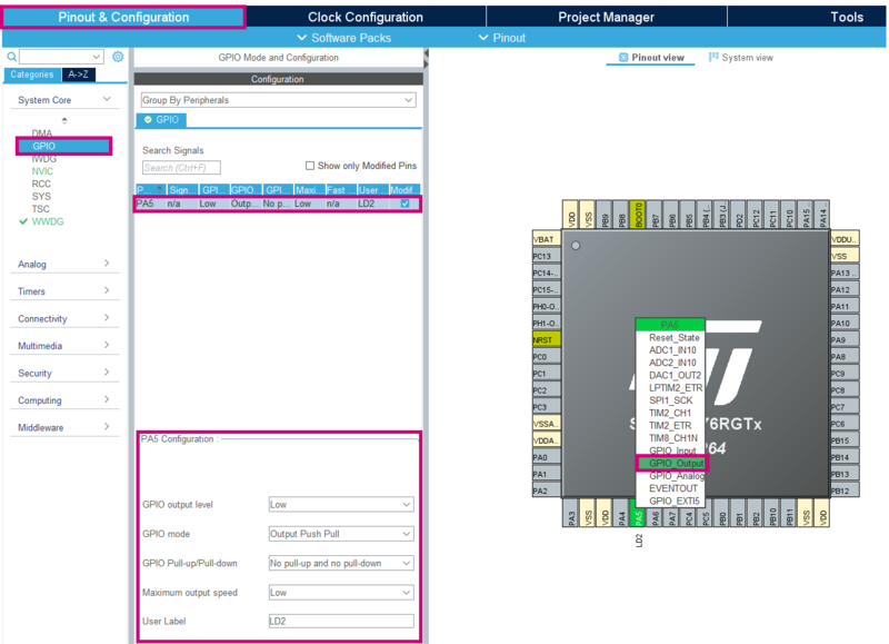
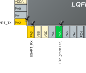
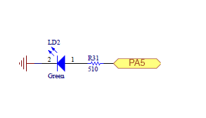
- In the Pinout & Configuration window, select GPIO and define PA5 as a GPIO_Output
- Keep the same configuration as following
- Low
- Output Push Pull
- No pull-up and pull-down
- Low
- LD2
3.4. WWDG Configuration
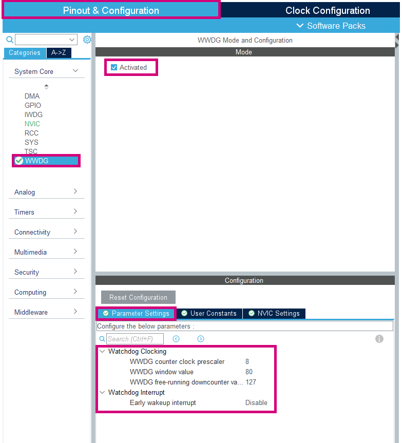
- In the same window, select WWDG and click on Activated
- Then go to Parameter Settings, and enter the following configuration
3.5. Clock Configuration
- In the Clock Configuration window, in the HCLK box, enter the maximum value for frequency : 80MHz
3.6. Generate project and edit main.c
The easiest way to generate the code is to save your current project : Ctrl + S
The code is generated so you can see it in the left side of the screen in the project explorer
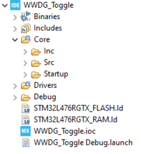
Now, open the main.c file which is the main source file for this application
- The LED toggling is done with a HAL function inside main.c
- You can calculate the delay with this formula:
 /* USER CODE BEGIN 3 */
  /* Infinite loop */
  {
    HAL_Delay(20);  // because (1/80000000)*4096*8*(127-80+1)) ~ 20ms
    HAL_GPIO_TogglePin(LD2_GPIO_Port, LD2_Pin);
    if (HAL_WWDG_Refresh(&hwwdg) != HAL_OK)
    {
        Error_Handler();
    }
  }
  /* USER CODE END 3 */
3.7. Compile and flash
Every 500 ms the green LED state changes.
4. Configure IWDOG with LED indication
4.1. Objective
- In this project, you will learn how to setup IWDG in STM32CubeIDE
- How to Generate Code in STM32CubeIDE and use HAL functions
- Create a simple application to test and periodically refresh the IWDG
- Verify the correct functionality on toggling LED
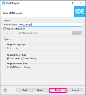
4.2. Create the project in STM32CubeIDE
File > New > STM32 Project in main panel.

In this example the NUCLEO-L476RG board is used.
- Select NUCLEO-L476RG in board Selector.
- Save the project.
4.3. GPIO Configuration
- In the Pinout & Configuration window, select GPIO and define PA5 as a GPIO_Output
- Keep the same configuration as following
- Low
- Output Push Pull
- No pull-up and pull-down
- Low
- LD2
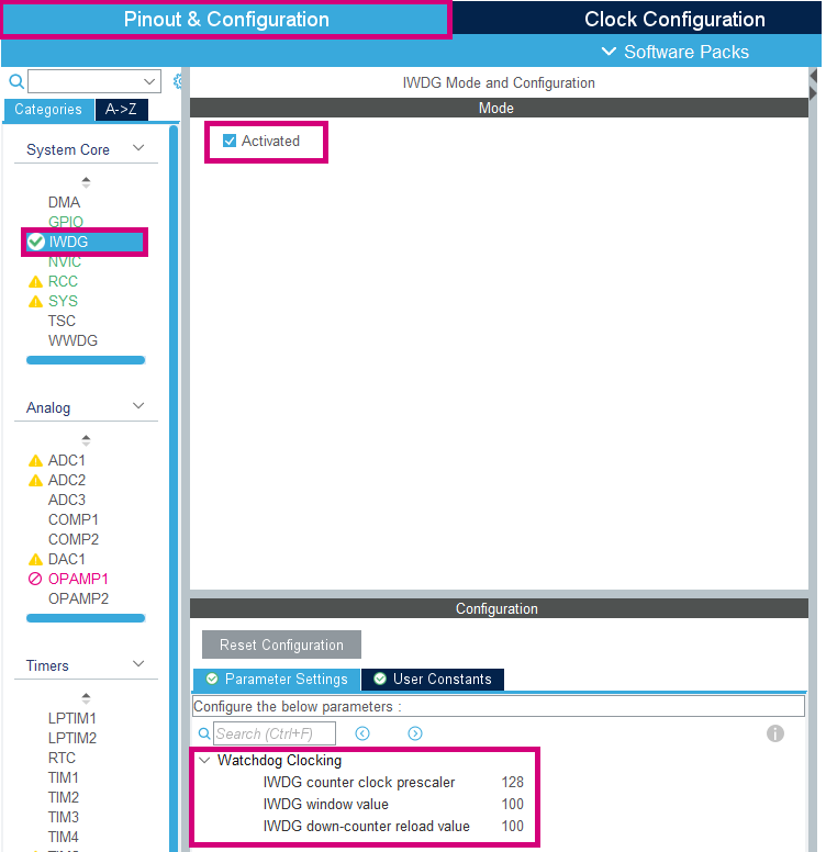
4.4. IWDG Configuration
- In the same window, select IWDG and click on Activated
- Then go to Parameter Settings, and enter the following configuration
4.5. Set the project details for generation
The easiest way to generate the code is to save your current project : Ctrl + S
The code is generated so you can see it in the left side of the screen in the project explorer
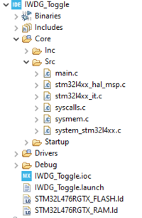
4.6. Open the main.c in our IDE
Now, open the main.c file which is the main source file for this application
- The LED toggling is done with a HAL function inside main.c
 /* USER CODE BEGIN 3 */
  /* Infinite loop */
  {
	HAL_Delay(300);  // because (1/32000)*128*100 so max ~400ms
	HAL_GPIO_TogglePin(LD2_GPIO_Port, LD2_Pin);
	if (HAL_IWDG_Refresh(&hiwdg) != HAL_OK)
	{
		Error_Handler();
	}
  }
  /* USER CODE END 3 */
4.7. Compile and flash
Every 300 ms the green LED state changes. The IWDG must be refresh before the downcounter reaches the end of counter value. The IWDG is set as following :
- Clock counter prescaler : 128
- Downcounter reload value : 100
Maximum time calculate before reset (if no refresh) First, we calculate the downcounter's frequency is (LSI/Clock Prescaler) = (32000/128) = 250Hz Then, we conclude the time for one clock cycle = 1/Frequence = 4ms So we can figure out that the maximum time before reset is the (time for one clock cycle) x (Reload value) = 0.004 x 100 = 400ms
[[category:Getting_started_with_STM32_system_peripherals | 60]]
