SFI Step-by-step on STM32H735G-DK![]() 75min
75min
Target description
This tutorial shows how to use SFI for installing a simple LED Blink example to STM32H735G-DK.
The process goes through three 'steps' at the Original Equipment Manufacturer (OEM) and the Contract Manufacturer (CM) sites.
- Development @ OEM : the application code that will run on STM32 is generated.
- Secure Room @ OEM : code prepared during the development is encrypted and packaged to be sent for manufacturing. The Secure Room is isolated and its resources are not visible outside of it.
- Manufacturing @ CM : the encrypted code received by the OEM Secure Room is installed using SFI tools.
Prerequisites
- knowledge of STM32CubeProgrammer
- knowledge of JTAG/UART/SPI
- STM32CubeMX introduction
Hardware
- STM32H735-DK[1] Discovery kit with STM32H735IG MCU
- STM32-HSM[2] SAM for Secure Firmware Installation
- SmartCard Reader
- Laptop Built-in
- External
- STLINK-V3[3] modular in-circuit debugger and programmer for STM32/STM8
- USB cable Type-A to Micro-B
- Jump wires
Software
- STM32CubeProgrammer[4] Software programming tool for STM32 (v2.10 min)
- Including STM32TrustedPackageCreator
- STM32CubeMX[5] STM32Cube initialization code generator
- STM32CubeIDE[6] Integrated Development Environment for STM32
Literature
- AN4992 STM32 MCUs secure firmware install (SFI) overview
- UM2237 STM32CubeProgrammer software description
- UM2238 STM32 Trusted Package Creator tool software description
- AN5054 Secure programming using STM32CubeProgrammer
- AN2606 STM32 microcontroller system memory boot mode
- RM0468 STM32H723/733, STM32H725/735 and STM32H730 Value line advanced Arm®-based 32-bit MCUs
- UM2679 STM32H735G-DK Discovery kit
- UM2448 STLINK-V3SET debugger/programmer for STM8 and STM32
1. Environment setup
Before starting, the first step is to prepare the environment to go through the SFI process.
1.1. Install STM32CubeProgrammer and STM32TrustedPackageCreator
![]() 5min
5min
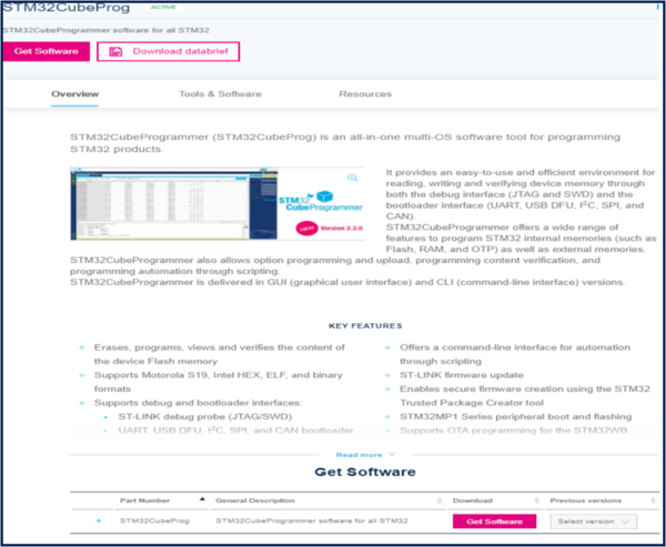
STM32CubeProgrammer (STM32CubeProg) is an all-in-one multi-OS software tool for programming STM32 products. STM32CubeProgrammer provides an easy-to-use and efficient environment for reading, writing and verifying device memory through both the debug interface (JTAG and SWD) and the bootloader interface (UART, USB DFU, I2C, SPI, and CAN).
STM32TrustedPackageCreator is part of the STM32CubeProgrammer tool set, and allows the generation of secure firmware and modules to be used for STM32 secure programming solutions.
- Download the latest version of STM32CubeProg[4]
- Unzip the downloaded file and launch the SetupSTM32CubeProgrammer-xxx.exe corresponding to your OS, and follow the instructions.

Make to sure to select STM32TrustedPackageCreator add-on during the installation of STM32CubeProgrammer
STM32CubeProgrammer and STM32TrustedPackageCreator are now installed on your computer.
1.2. Install STM32CubeMX
![]() 10min
10min
STM32CubeMX is a graphical tool that allows an easy configuration of STM32 microcontrollers and the generation of the corresponding initialization C code through a step-by-step process.
Please refer to the STM32CubeMX install on the Step1 Tools installation
STM32CubeMX is now installed on your computer.
1.3. Install STM32CubeIDE
![]() 10min
10min
STM32CubeIDE is an Integrated Development Environment for STM32
Please refer to the STM32CubeIDE install on the article: Step1 Tools installation
2. Development @ OEM
The first step of the process is to create a demo LED Blink application with STM32CubeMx for STM32H735G-DK. You can find a detailed step-by-step for Nucleo-L476RG in the Step2 Blink LED article - the process is similar.
2.1. Create New Project using STM32CubeMX
![]() 5min
5min
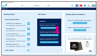
- Run STM32CubeMX tool.
- Click New Project or Menu -> File -> New Project.
- From Board Selector section, filter to select:
- Check Discovery Kit type.
- Check STM32H7 on MCU Series.
- Select STM32H735G-DK board using Board selector:
- Check Discovery Kit type.

- Click Start Project to continue.
- Answer No to the popup Initialize all peripherals with their default Mode ?
- Click Start Project to continue.
2.2. Pinout Configuration
![]() 5min
5min
When a board is selected, STM32CubeMX allows automatically the pinout setting for the board with the pin assignments for the communication interfaces, LEDs, and other functions.
You can refer to UM2679 STM32H735G-DK Discovery kit (MB1520) for a description of the pinout of the board.
For this example we will use the green LED pin LD1 (PC3) and the red LED pin LD2 (PC2) present on the STM32H735G-DK board as GPIO_Output.
2.3. Clock Configuration
![]() 4min
4min
In the Clock Configuration tab, check that STM32CubeMX automatically configures the internal oscillator in the clock system with PLL @96MHz.
File:CubeMX STM32H735-DK Default Clock.png
For the sake of this demonstration this configuration is sufficient, you can refer to RM0468 for other configuration options for STM32H735.
2.4. Configure project and generate source code
![]() 4min
4min
Switch to the Project Manager tab to configure the project. In the Project tab:
- Fill the Project Name and Project Location fields
- In this example we will use Project Location = 'C:\SFI_test' and Project Name = 'H735_LedBlink'
- Set Toolchain/IDE to STM32CubeIDE.
File:CubeMX STM32H735-DK Project Generation.png
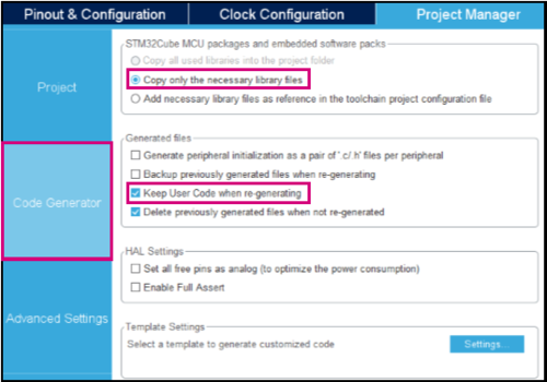
In the Code Generator tab, ensure that the following options are checked:
- In STM32Cube Firmware Library Package section: Copy only the necessary library files .
- In Generated files section: Keep user code when regenerating the C code option.

To generate the project for STM32CubeIDE:
- Click on Generate Code.

- Click on Open Project to open the project with STM32CubeIDE.
File:CubeMX STM32H735-DK open project popup.png
2.5. Edit main.c to toggle the LED
![]() 4min
4min
In STM32CubeIDE, from the Project Explorer tab, open main.c in the Src folder and add the following code inside the while (1)
loop between /* USER CODE BEGIN 3 */ and /* USER CODE END 3 */ section (this will preserve your code after regeneration).
HAL_GPIO_TogglePin(GPIOC, GPIO_PIN_3);
/* Insert delay 100 ms */
HAL_Delay(100);
HAL_GPIO_TogglePin(GPIOC, GPIO_PIN_2);
/* Insert delay 100 ms */
HAL_Delay(100);
File:CubeIDE STM32H735-DK main LEDs blinking.png
2.6. Build the project
![]() 2min
2min
To power the STM32H735G-DK, use its CN15 connector to connect in with a computer through a USB Type-A to Micro-B cable.
Click on the project from the project explorer, then right click and select Build Project, to compile the project (or click on Build button ![]() on the toolbar).
on the toolbar).
Save the generated file created in <Project Location>\Debug\<Project Name>.bin to a 'ROOT_FOLDER'
- In our example: C:\SFI_test\Debug\H735_LedBlink.bin
2.7. Debug the project
![]() 2min
2min
Click on the Debug toolbar icon ![]() to start the debug session (or in the menu, select Run > Debug).
to start the debug session (or in the menu, select Run > Debug).
Click OK on the Debug configuration window.
File:CubeIDE STM32H735-DK debug configuration.png
Click on Resume (F8) icon ![]() to continue the execution.
to continue the execution.
Now watch the green LED (LD1) and red LED (LD2) toggling on the STM32H735G-DK board.
3. Secure Room @ OEM
In the Secure Room the following two steps are performed:
- SFI package generation: the code prepared during the development is encrypted and packaged to be sent for manufacturing.
- HSM Provisioning: the HSM is provisioned with the keys used for encryption and with the max license counter.
3.1. SFI package generation
![]() 10min
10min
In this step, the application binary file and the option byte configuration are encrypted in an SFI package.
The following inputs are needed:
- Application Binary file (created in the previous step) and dowload address in FLASH.
- AES Key
- Nonce
- Option bytes
3.1.1. Download address
The OEM binary file is designed to be executed from a specific address in FLASH. The SFI process ensures that the binary is downloaded at the address specified as input parameter.
- For this example we will use: 0x08000000
3.1.2. Key generation
First step is to create secret keys and the nonce that will be used by STM32TrustedPackageCreator to encrypt the firmware image in the SFI package and will be programmed in the STM32-HSM.
3.1.2.1. AES Key
- Create a new text file
- Paste the following text
AES_KEY_TEST_001- The corresponding hex values are: 41 45 53 5F 4B 45 59 5F 54 45 53 54 5F 30 30 31
- Save it as aeskey.bin
3.1.2.2. AES Nonce
- Create a new text file
- Paste the following text
NONCE_TEST01- The corresponding hex values are: 4E 4F 4E 43 45 5F 54 45 53 54 30 31
- Save it as nonce.bin
3.1.3. Option bytes
Together with installing the application binary, SFI process can be used to specify the OB values to be configured at the end of the installation process.
In the path C:\Program Files\STMicroelectronics\STM32Cube\STM32CubeProgrammer\bin\SFI_OB_CSV_FILES you can find file examples for each series of MCUs.
To create your OB file, you can use STM32 Trusted Package Creator :
- Open STM32 Trusted Package Creator
- In SFI OB tab, select the MCU used. In this example please select STM32H2x/H3x.
- The right panel displays the OB values as saved in the file you generate. Please select a path to save the OB file that will be generated in "Generate OB .csv file"

- Microcontroller panel is useful to choose the OB values you want to use. Once you select "Generate OB" button, OB values are displayed in "Option bytes generated values" panel, and a file is created / updated with the values chosen.

In this example we have generated these values :
FOPTSR_PRG,0xDFDFAAF3
FPRAR_PRG_A,0xF100F200
FSCAR_PRG_A,0xF100F200
FWPSN_PRG_A,0xFFFFFF
FBOOT7_PRG,0x1FF10800
In the following a description of the values
- FOPTSR_PRG,0xDFDFAAF3
- IO_HSLV : 0x0 (Product working in the full voltage range, I/O speed optimization at low-voltage disabled)
- SECURITY : 0x0 (Security feature disabled)
- ST_RAM_SIZE : 0x3 (16 KB)
- FZ_IWDG_SDBY : 0x1 (Independent watchdog is running in STANDBY mode)
- FZ_IWDG_STOP : 0x1 (Independent watchdog is running in STOP mode)
- RDP : 0xAA (Level 0)
- NRST_STBY : 0x1 (STANDBY mode on Domain 1 is entering without reset)
- NRST_STOP : 0x1 (STOP mode on Domain 1 is entering without reset)
- IWDG1_SW : 0x1 (Independent watchdog is controlled by software)
- BOR_LEV : 0x0 (BOR OFF)
- FPRAR_PRG_A,0xF100F200
- DMEP : 0x1 (Flash Bank PCROP zone is erased when RDP level regression (change from level 1 to 0) occurs)
- PROT_AREA_END: 0x100 (0x80100FF)
- PROT_AREA_START: 0x200 (0x8020000)
- FSCAR_PRG_A,0xF100F200
- DMES : 0x1 (Flash Bank secure area is erased when RDP level regression (change from level 1 to 0) occurs)
- SEC_AREA_END: 0x100 (0x80100FF)
- SEC_AREA_START: 0x200 (0x8020000)
- FWPSN_PRG_A,0xFFFFFF
- nWRP0 : 0x1 (Write protection not active on this sector)
- nWRP1 : 0x1 (Write protection not active on this sector)
- nWRP2 : 0x1 (Write protection not active on this sector)
- nWRP3 : 0x1 (Write protection not active on this sector)
- nWRP4 : 0x1 (Write protection not active on this sector)
- nWRP5 : 0x1 (Write protection not active on this sector)
- nWRP6 : 0x1 (Write protection not active on this sector)
- nWRP7 : 0x1 (Write protection not active on this sector)
- FBOOT7_PRG,0x1FF10800
- BOOT_CM7_ADD1: 0x1FF1 (0x1FF10000)
- BOOT_CM7_ADD0: 0x800 (0x8000000)
3.1.4. Output generation
- Preparation
In order to generate the SFI package we need too more parameters :
- ram size : Size of RAM memory available for SFI programming.
- token address : Address at which to store the Continuation token. The address must not collide with other areas.
For STM32H735 we preconize RAM Size = 0x1E000 and token address = 0x080F 0000.
Output generation with STM32 Trusted Package Creator CLI this command line allows the package generation
STM32TrustedPackageCreator_CLI.exe -sfi -fir H735_LedBlink.bin 0x08000000 -k aeskey.bin -n nonce.bin -ob ob.csv -v 1 --ramsize 0x1E000 --token 0x80F0000 -o H735_LedBlink.sfi
The command will create the H735_LedBlink.sfi package (you can change the verbose level of the command with the parameter -v 1,2,3)
Output generation with STM32 Trusted Package Creator GUI
3.2. HSM programming
![]() 10min
10min
The programming step consists in the provisioning to the HSM of the following parameters:
- AES Key
- Nonce
- Personalization data
- ID
- License counter
3.2.1. Preparation
AES Key and Nonce have been generated in the previous step - in this section we will focus on the remaining parameters.
3.2.2. HSM programming using STM32 Trusted Package Creator - GUI (Graphical User Interface)
Open the tool STM32 Trusted Package Creator.
If the shortcut has not been created on your Desktop during STM32CubeProgrammer installation, you can open it from :
C:\Program Files\STMicroelectronics\STM32Cube\STM32CubeProgrammer\bin
- Firmware identifier
The ID is a tag name for the HSM card (i.e. for the secret key) that could be useful to the CM when multiple cards are being used in manufacturing. For this example we will use: h735_4830100C
- Encryption key file
Enter the AES Key file previously generated.
- Nonce file
Enter the Nonce generated in previous step.
- Personalization data file
You have to select the MCU used : in our case, please select STM32H7.
Press Open, and select PersoPackages folder.
In this folder you can find the file to use:
STM32H7_45001001_SFI._01000000_00000000.enc.bin
- Maximum number of images to program
Maximum number of devices that can be programmed with this HSM. For this example we will use: 300
- Provisionning
Now that we have defined the parameters, we can proceed with the provisioning of the STM32-HSM.
- Plug the HSM into the smart card reader
- Provision the HSM :
Select ""Program HSM""The HSM is ready to be shipped to the CM together with the H735_LedBlink.sfi package created before.
3.2.3. HSM programming with STM32 Trusted Package Creator - CLI (Command Line Interface)
- Personalization data
The first step for HSM programming is to retrieve the personalization data for the smartcard: with this step, the specific STM32-HSM will allow the installation of SFI images to a specific STM32 family of products. This allows the OEM to add an additional control on the STM32 parts that will be manufactured by the CM.
To perform this operation the user first needs to know the product ID of the device.
- Connect the STM32H735G-DK board with the micro USB cable through CN15
- Retrieve the STM32 device certificate
STM32_Programmer_CLI.exe -c port=SWD mode=HOTPLUG -gc H735_certificate.bin
- Open the H735_certificate.bin file with an hex editor and read the first 8 bytes or with STM32CubeProgrammer and read the ASCII code (i.e. the product ID) - for H735 it will be 4830100C
- Browse now to the folder C:\Program Files\STMicroelectronics\STM32Cube\STM32CubeProgrammer\bin\PersoPackages and look for the binary file with the corresponding name - in this case the parameter for the command will be
c:\Program Files\STMicroelectronics\STM32Cube\STM32CubeProgrammer\bin\PersoPackages\4830100C_SFI._01000000_00000000.enc.bin
- ID
The ID is a tag name for the HSM card (i.e. for the secret key) that could be useful to the CM when multiple cards are being used in manufacturing.
- For this example we will use: h735_4830100C
- License counter
License counter is the max number of devices that can be programmed with this HSM.
- For this example we will use: 300
- Provisioning
Now that we have defined the parameters, we can proceed with the provisioning of the STM32-HSM.
- Plug the HSM into the smart card reader
- We can get the state of the HSM with the command:
STM32TrustedPackageCreator_CLI.exe -hsm -i 1 -info
- Provision the HSM :
STM32TrustedPackageCreator_CLI.exe -hsm -i 1 -k aeskey.bin -n nonce.bin -id "h735_4830100C" -mc 300 -pd 'c:\Program Files\STMicroelectronics\STM32Cube\STM32CubeProgrammer\bin\PersoPackages\4830100C_SFI._01000000_00000000.enc.bin'
You can get the state of the HSM with the command:
STM32TrustedPackageCreator_CLI.exe -hsm -i 1 -info
The HSM is ready to be shipped to the CM together with the H735_LedBlink.sfi package created before.
4. Manufacturing @ CM
In this step, the CM receives from the OEM the HSM card provisioned with the secret key and initialized with a max counter of licenses, and the .sfi package to be installed (including the firmware in encrypted form and the option bytes configuration).
The SFI process could be performed through a regular JTAG/SWD interface or through the system bootloader interface (you can refer to AN2606 for details on the supported interface for each microcontroller). The following section will cover JTAG/SWD, USART and SPI interfaces - each section will include the following sections :
- Hardware connection
- Option Bytes regression (optional)
- Secure Firmware Install
4.1. SWD interface
 6min
6min
4.1.1. Hardware connection
Plug a micro USB cable to CN15 and make sure that JP7 is in the CHGR position.
4.1.2. Option bytes regression
The following steps will configure the device to regress the option bytes configuration to a default state:
STM32_Programmer_CLI.exe -c port=SWD mode=HOTPLUG -ob RDP=0xAA nWRP0=1 nWRP1=1 nWRP2=1 nWRP3=1 nWRP4=1 nWRP5=1 nWRP6=1 nWRP7=1 BOOT_CM7_ADD0=0x0800 BOOT_CM7_ADD1=0x1FF0 SECURITY=0 -e all -ob displ
After this step the device is ready for the SFI process.
4.1.3. Firmware install
This command will start the SFI process and proceed with the installation.
STM32_Programmer_CLI.exe -vb 1 -c port=SWD mode=HOTPLUG -sfi H735_LedBlink.sfi hsm=1 slot=1
After this step the device is programmed with the OEM application code.
4.2. UART interface
10min
4.2.1. Hardware connection
The possible hardware connection is the one using the STM32H735G-DK on-board STLINK.
To get the UART COM port you can :
- Open device manager and check the COM port associated with the on-board STLINK (since the used UART pins are available on STLINK VCP).
In this case we will use COM39.
In order to enable the system bootloader at boot the following connection is needed :
- Switch SW1 to position 1 (SYS MEM) in order to enable the system bootloader
Then :
- Plug a micro USB cable to CN15 and make sure that JP7 is in the CHGR position.
- Reset the board.
The STM32H735G-DK on-board STLINK can be used as USART bridge to STM32H735 system bootloader. To use the USART bootloader (USART3 PD8/PD9), no hardware modifications are needed.
4.2.2. Option bytes regression
The following steps will configure the device to regress the option bytes configuration to a default state:
STM32_Programmer_CLI.exe -c port=COM39 br=115200 -rdu
- Note:The COM port may be different on your system - make sure to update it in the commands.
Press the BLACK RESET button on the board
STM32_Programmer_CLI.exe -c port=COM39 br=115200 -ob RDP=0xAA nWRP0=1 nWRP1=1 nWRP2=1 nWRP3=1 nWRP4=1 nWRP5=1 nWRP6=1 nWRP7=1 BOOT_CM7_ADD0=0x0800 BOOT_CM7_ADD1=0x1FF0 SECURITY=0 -e all -ob displ
- Note:The COM port may be different on your system - make sure to update it in the commands.
After this step the device is ready for the SFI process.
4.2.3. Firmware install
This command will start the SFI process and proceed with the installation.
STM32_Programmer_CLI.exe -vb 1 -c port=COM39 br=115200 -sfi H735_LedBlink.sfi hsm=1 slot=1
- Note:The COM port may be different on your system - make sure to update it in the commands.
Switch SW1 to position 0 (FLASH) then reset the Board to start the program in user FLASH. After this step the device is programmed with the OEM application code.
4.3. SPI interface
10min
In order to enable the system bootloader at boot the following connection is needed:- Switch SW1 to position 1 (SYS MEM) in order to enable the system bootloader at boot
Then
- Plug a micro USB cable to CN15 and make sure that JP7 is in the CHGR position.
- Reset the board.
4.3.1. Hardware connection
10min
For this step, a STLINK-V3[3] is needed.Prepare the following connections:
- Disco CN19.29 (PE12) --> STLINK-V3 CN9.4 (SPI_SCK)
- Disco CN19.22 (PE13) --> STLINK-V3 CN9.3 (SPI_MISO)
- Disco CN8.6 (PE14) --> STLINK-V3 CN9.2 (SPI_MOSI)
- Disco CN19.10 (PE11) --> STLINK-V3 CN9.1 (SPI_NSS)
- Disco CN19.30 (GND) --> STLINK-V3 CN9.5 (GND)
4.3.2. Option bytes regression
4min
The following steps will configure the device to regress the option bytes configuration to a default state:STM32_Programmer_CLI.exe -c port=SPI br=6000 -rdu
Press the BLACK RESET button on the board
STM32_Programmer_CLI.exe -c port=SPI br=6000 -ob RDP=0xAA nWRP0=1 nWRP1=1 nWRP2=1 nWRP3=1 nWRP4=1 nWRP5=1 nWRP6=1 nWRP7=1 BOOT_CM7_ADD0=0x0800 BOOT_CM7_ADD1=0x1FF0 SECURITY=0 -e all -ob displ
After this step the device is ready for the SFI process.4.3.3. Firmware install
2min
This command will start the SFI process and proceed with the installation.
STM32_Programmer_CLI.exe -vb 1 -c port=SPI br=6000 -sfi H735_LedBlink.sfi hsm=1 slot=1
Switch SW1 to position 0 (FLASH) then reset the Board to start the program in user FLASH. After this step the device is programmed with the OEM application code.
5. References