This article explain what is and how to use GPIO through examplesl
1. GPIO definition
Stands for General Purpose Input/Output. GPIO is a type of pin found on an integrated circuit that does not have a specific function. While most pins have a dedicated purpose, such as sending a signal to a certain component, the function of a GPIO pin is customizable and can be controlled by software.
2. Configure GPIO for LED toggling
2.1. Objective
- Learn how to setup the pin and GPIO port in STM32CubeMX
- Modify the code generated by STM32CubeMX and use the HAL functions
2.2. How
- Configure the GPIO pin in STM32CubeMX and generate the code
- Add into the project the HAL_Delay function and HAL_GPIO_Toggle function
- Verify the correct functionality on toggling LED
2.3. Create the project in STM32CubeMX
- New project > Access to board selector on main panel or Menu > File > New Project
- Select NUCLEO-L476RG
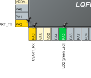
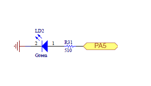
- if you have chosen to start the project with a board, the LED pin is already selected (PA5 on NucleoL476RG, for other board check the user manual)
Note: whenever you download a firmware package with STM32CubeMX you have existing examples. You can find them for example here: c:\Users\YourUserName\STM32Cube\Repository\STM32Cube_FW_G0_V1.3.0\Projects\NUCLEO-G071RB\Examples\GPIO\GPIO_IOToggle\GPIO_IOToggle.ioc and open them with STM32CubeMX.
2.3.1. GPIO configuration
- Select the Push-pull mode
- No pull-up and pull-down
- Output speed to VERY HIGH is important for faster peripherals like SPI, USART
2.3.2. GPIO(Pin) output speed configuration
- Change the rising and falling edge when the pin state changes from high to low or low to high
- A higher GPIO speed increases the EMI noise from STM32 and increases the STM32 consumption
- It is good to adapt the GPIO speed with the peripheral speed. Ex.: Toggling GPIO on 1Hz is LOW optimal settings, but with SPI on 45MHz the VERY HIGH must be set
2.3.3. Set the project details for generation
2.3.4. Open the main.c in our IDE
- We do the LED toggling in a function inside main.c
 /* USER CODE BEGIN 3 */
  /* Infinite loop */
  while (1)
  {
    HAL_GPIO_WritePin(GPIOG, GPIO_PIN_14, GPIO_PIN_SET);
    HAL_Delay(500);

    HAL_GPIO_WritePin(GPIOG, GPIO_PIN_14, GPIO_PIN_RESET);
    HAL_Delay(500);
  }
  /* USER CODE END 3 */
2.4. Compile and flash
- Every 500ms the green LED state changes.

