Registered User mNo edit summary |
Registered User mNo edit summary |
||
| Line 1: | Line 1: | ||
MB1263 board overview. | |||
== Board overview == | == Board overview == | ||
| Line 47: | Line 42: | ||
== Links == | == Links == | ||
[[STM32MP15 resources#MB1263 schematics|MB1263 schematics]] | [[STM32MP15 resources#MB1263 schematics|MB1263 schematics]] | ||
<noinclude> | |||
{{PublicationrequestId | 7568 | 2018-06-19 | AlainF}} | |||
[[Category:STM32MP15 Evaluation boards]] | |||
[[Category:STM32MP15]] | |||
[[Category:ST boards]] | |||
</noinclude> | |||
Revision as of 15:32, 14 October 2019
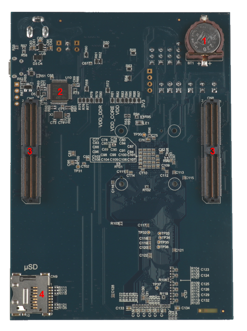
MB1263 board overview.
1. Board overview[edit source]
Daughterboard MB1263 (STM32MP157x 18x18 with PMIC and DDR3), revision C-0.1: part of the STM32MP157x-EV1 Evaluation board
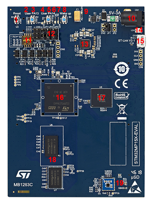
Details of some LEDs:
- LD1: green if power connection established
- LD6: red flashing if ST-LINK/V2-1 connection not established, else green
- LD2, LD3, LD4, LD5: some user LEDs are used to reflect the system activity, whereas the others are left free and can be directly used by the application, as explained in the LEDs and buttons on STM32 MPU boards article